Solar cell and supercapacitor integrated device and manufacturing method thereof

A technology for supercapacitors and solar cells, applied in the direction of capacitor current collector combinations, etc., can solve the problems of low photoelectric energy conversion and storage efficiency, difficulty in reducing the size, and complicated device connections, so as to increase the area, reduce the size of the device, and simplify the connection. Effect

Inactive Publication Date: 2018-12-11
SHANGHAI INTEGRATED CIRCUIT RES & DEV CENT
2 Cites 4 Cited by

AI-Extracted Technical Summary

Problems solved by technology

[0002] The research on solar cells and supercapacitors shows that usually people make solar cells and supercapacitors separately and independently, and then conne...

Method used

In summary, the solar cell and supercapacitor integrated device provided by the present invention and its manufacturing method, the solar cell and supercapacitor integrated device include a substrate, a supercapacitor that surrounds the substrate, a supercapacitor that surrounds the substrate A first bushing on the supercapacitor and a solar cell surrounding the first bushing. Wherein, the supercapacitor includes a first electrode, a first electrolyte, and a second electrode that surround the substrate sequentially from the inside to the outside; the solar cell includes a first electrode that surrounds the first casing sequentially from the inside to the outside. Three electrodes, a fourth electrode, a second sleeve, and a second electrolyte filled between the first sleeve and the second sleeve. The solar cell and supercapacitor integrated device and its manufacturing method can arrange the supercapacitor as an energy storage unit inside the solar cell as a photoelectric conversion unit, which simplifies the connection between devices, reduces the size of the device, and has the same size as Compared with other devices, the areas of solar cells and supercapacitors are increased, so that the efficiency of photoelectric energy conversion and energy storage is improved, and thus a coaxial integrated device with high-efficiency photoelectric conversion and energy storage is formed; further, in The active material in the first electrode and the second electrode can increase the capacitance and energy density of the capacitor, increase the contact specific surface area of ​​the electrode surface, thereby enhancing the capacitance; furthermore, each layer of the integrated device can be a flexible material , the integrated device can collect incident light at various angles to obtain electrical energy, and the flexible integrated device can be woven into the fabric, so as to be applied to the next generation of wearable electronic devices.
One embodiment of the present invention provides a kind of solar cell and supercapacitor integrated device, referring to Fig. 1a and Fig. 1b, Fig. 1a is the structural representation of the solar cell and supercapacitor integrated device of one embodiment of the present invention, Fig. 1b is a diagram Schematic side cross-sectional view of the integrated solar cell and supercapacitor device shown in 1a. It can be seen from Fig. 1a and Fig. 1b that the solar cell and supercapacitor integrated device of this embodiment includes a substrate 100, a supercapacitor 200 surrounding the substrate 100, and a first bushing surrounding the supercapacitor 200 300 and the solar cell 400 surrounding the first sleeve 300 . Wherein, the supercapacitor 200 includes a first electrode 210, a first electrolyte 220, a...

Abstract

The invention provides a solar cell and supercapacitor integrated device and manufacturing method thereof..The integrated device is formed on a substrate from the inside to the outside around the substrate, a first sleeve and a solar cell, wherein the supercapacitor comprises a first electrode, a first electrolyte, a second electrode sequentially surrounding the substrate from inside to outside,,the solar cell comprises a third electrode, a fourth electrode, a second sleeves equentially surrounding the first sleeve from inside to outside, and a second electrolyte filled between the first sleeve and the second sleeve. The integrated device arranges the supercapacitor inside the solar cell, thus simplifies the connection between the devices, reduces the size of the device, and further formsa coaxial integrated device in which efficient photoelectric conversion and energy storage are integrated; At the same time, each layer of the integrated device may be a flexible material, so that the integrated device as a whole has flexibility and flexibility.

Application Domain

Capacitor collector combinations

Technology Topic

Image

  • Solar cell and supercapacitor integrated device and manufacturing method thereof
  • Solar cell and supercapacitor integrated device and manufacturing method thereof
  • Solar cell and supercapacitor integrated device and manufacturing method thereof

Examples

  • Experimental program(1)

Example Embodiment

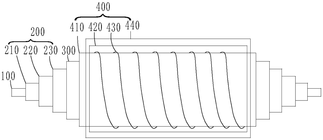
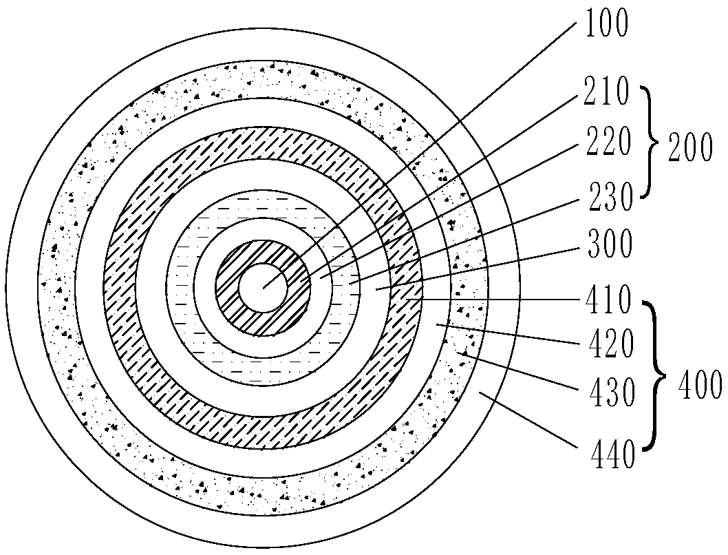
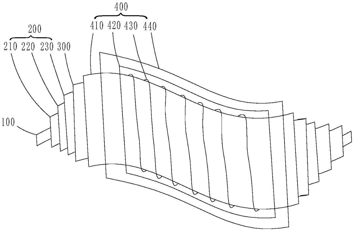
[0034] In order to make the purpose, advantages and features of the present invention clearer, the following is attached Figure 1a~4 The integrated device of solar cell and supercapacitor proposed by the present invention and its manufacturing method will be described in further detail. It should be noted that the drawings are in a very simplified form and all use imprecise proportions, which are only used to conveniently and clearly assist in explaining the purpose of the embodiments of the present invention.
[0035] An embodiment of the present invention provides a solar cell and supercapacitor integrated device, see Figure 1a with Figure 1b , Figure 1a It is a schematic structural diagram of a solar cell and supercapacitor integrated device according to an embodiment of the present invention, Figure 1b Yes Figure 1a The side cross-sectional schematic diagram of the solar cell and supercapacitor integrated device shown. From Figure 1a with Figure 1b It can be seen that the solar cell and supercapacitor integrated device of this embodiment includes a substrate 100, a supercapacitor 200 surrounding the substrate 100, a first sleeve 300 surrounding the supercapacitor 200, and The solar cell 400 on the first sleeve 300. Wherein, the super capacitor 200 includes a first electrode 210, a first electrolyte 220, and a second electrode 230 sequentially surrounding the substrate 100 from the inside to the outside; the solar cell 400 includes a first electrode 210, a first electrolyte 220, and a second electrode 230 surrounding the substrate 100 from the inside to the outside. The third electrode 410, the fourth electrode 430, the second sleeve 440 on a sleeve 300, and the second electrolyte 420 filled between the first sleeve 300 and the second sleeve 440. The solar cell and supercapacitor integrated device has the supercapacitor 200 as the energy storage unit arranged inside the solar cell 400 as the photoelectric conversion unit, which simplifies the connection between the devices, reduces the device size, and is compatible with devices of the same size. In comparison, the area of ​​the solar cell 400 and the supercapacitor 200 have been increased, so that the efficiency of photoelectric energy conversion and energy storage can be improved, thereby forming a coaxial integrated device that integrates efficient photoelectric conversion and energy storage. Also, see Figure 1c , Figure 1c It is a schematic structural diagram of a solar cell and supercapacitor integrated device according to another embodiment of the present invention, from Figure 1c It can be seen that when the substrate 100, the first sleeve 300, the layers in the supercapacitor 200, and the layers in the solar cell 400 are all flexible materials, the resultant is flexible and bendable. Integrated device, the flexible integrated device can collect incident light at various angles to obtain electric energy, so that it can be applied in a space full of diffused light; at the same time, the flexible integrated device can be woven into the fabric, plus its own independent power supply The system enables the flexible integrated device to be applied to next-generation wearable electronic equipment.
[0036] The material of the substrate 100 may be a columnar structure material, including a rigid substrate or a flexible substrate, the columnar rigid substrate may be glass fiber or silicon carbide fiber, etc., and the columnar flexible substrate may be rubber fiber. , Polyurethane fiber, polytetrafluoroethylene fiber, quartz fiber, carbon fiber and carbon fiber reinforced epoxy resin composite material one or more.
[0037] The super capacitor 200 surrounds the outer surface of the substrate 100, and the super capacitor 200 includes a first electrode 210, a first electrolyte 220, and a second electrode 230 surrounding the substrate 100 in order from the inside to the outside.
[0038] The first electrode 210 is a positive electrode. The structure of the first electrode 210 may include a carbon electrode and an active material attached to the carbon electrode. The carbon electrode may be oriented multi-walled carbon nanotubes, graphene, or carbon nanofibers. , One or more of carbon nanoparticles, the active material may be one or more of polyaniline, polypyrrole, manganese dioxide, tin dioxide and graphene. The active material can increase the capacitance of the supercapacitor 200. For example, polypyrrole or polyaniline can increase the pseudocapacitance effect, transfer charge in a short time, and increase the capacitance and energy density of the capacitor, while graphene can greatly Increase the contact surface area of ​​the carbon electrode surface, thereby enhancing the capacitance.
[0039] The first electrolyte 220 includes a solid electrolyte, and the first electrolyte 220 can separate the first electrode 210 and the second electrode 230 by the first electrolyte 220 to prevent short circuits. The first electrolyte 220 may be one or more of polyvinyl alcohol/phosphoric acid electrolyte, polyvinyl alcohol/sulfuric acid electrolyte, and polyvinyl alcohol/potassium hydroxide electrolyte.
[0040] The second electrode 230 is a negative electrode. The structure of the second electrode 230 may include a carbon electrode and an active material attached to the carbon electrode. The carbon electrode may be oriented multi-walled carbon nanotubes, graphene, or carbon nanofibers. , One or more of carbon nanoparticles, the active material may be one or more of graphene, mesoporous carbon, silicon, germanium and tin. The active material on the second electrode 230 can increase the capacitance of the supercapacitor 200 the same as the active material on the first electrode 210.
[0041] The first sleeve 300 may be a cylindrical tube or a square tube, and the material of the first sleeve 300 may be polyethylene, PET, FEP, PFA, PTFE, or polyurethane. The two ends of the first sleeve 300 are sealed to seal the supercapacitor 200 inside to separate the supercapacitor 200 from the solar cell 400, thereby preventing the first electrolyte 220 of the supercapacitor 200 from the second electrolyte 220 of the solar cell 400 The mutual penetration between the electrolytes 420 and current crosstalk.
[0042] The solar cell 400 surrounds the outer surface of the first sleeve 300, the solar cell 400 may be a dye-sensitized cell, and the solar cell 400 includes the first sleeve 300 sequentially surrounding from the inside to the outside. The upper third electrode 410, the fourth electrode 430, the second sleeve 440, and the second electrolyte 420 are filled and sealed between the first sleeve 300 and the second sleeve 440.
[0043] The third electrode 410 is a counter electrode, and the third electrode 410 includes a carbon electrode, which may be one or more of oriented multi-walled carbon nanotubes, graphene, carbon nanofibers, and carbon nanoparticles.
[0044] The second electrolyte 420 includes an electrolyte, the second electrolyte 420 may be composed of a redox pair and a solvent, and the redox pair may contain 4-tert-butylpyridine, iodine and lithium iodide, 1,2- A composition of dimethyl-3-propylimidazolium iodine, or a composition containing bromine, lithium bromide, and 1,2-dimethyl-3-propylimidazolium bromide; the solvent can be acetonitrile, propionitrile, γ- Butyrolactone or γ-valerolactone, etc.
[0045] The fourth electrode 430 is a photoanode, the fourth electrode 430 may be spirally wound on the outer surface of the third electrode 410, and the structure of the fourth electrode 430 may include a spiral conductive wire and attached to the conductive wire Wherein, the conductive wire can be one or more of titanium wire, tantalum wire, nickel wire, steel wire and carbon fiber wire, and the material of the metal oxide film layer can be titanium dioxide, One or more of cobalt tetroxide, nickel oxide, nickel cobalt oxide and manganese dioxide, and the structure of the metal oxide film layer is nanotubes vertically arranged on the outer surface of the conductive wire.
[0046] The second sleeve 440 may be a light-transmitting insulating material with a light transmittance of 30% to 100%, and the light-transmitting insulating material is, for example, glass tube, polyethylene, PET, FEP, PFA, PTFE, or polyurethane. The second sleeve 440 may be a cylindrical tube or a square tube. After the second electrolyte 420 is filled, the two ends are sealed.
[0047] Figure 4 Yes Figure 1a The schematic diagram of the charging and discharging circuit of the solar cell and supercapacitor integrated device shown, from Figure 4 It can be seen that the switch device capable of turning on or off the electrical connection is arranged between the super capacitor 200 as the energy storage unit and the solar cell 400 as the photoelectric conversion unit, and the light is transmitted from the light-transmitting second sleeve 440 The solar cell 400 is taken in, and the solar cell 400 converts the captured light energy into electrical energy to charge the super capacitor 200. Specifically, the fourth electrode 430 in the solar cell 400 may be connected to the first electrode 210 in the supercapacitor 200, while the third electrode 410 in the solar cell 400 is connected to the second electrode 230 in the supercapacitor 200, When the switch K1 is opened and the switches K2 and K3 are closed, the solar battery 400 charges the super capacitor 200. In addition, the first electrode 210 and the second electrode 230 in the supercapacitor 200 can be connected to an external device D1 (such as a bulb, a resistor, etc.). When K2 and K3 are disconnected and K1 is closed, the supercapacitor 200 discharges.
[0048] In addition, the fourth electrode 430 in each solar cell 400 may be connected to the third electrode 410 in the adjacent solar cell 400 to realize the series connection of a plurality of solar cells 400.
[0049] This embodiment also provides a method for manufacturing a solar cell and supercapacitor integrated device, such as figure 2 It is a flowchart of a manufacturing method of a solar cell and supercapacitor integrated device according to an embodiment of the present invention, Figure 3a~3f Yes figure 2 The illustrated schematic diagram of the device structure in the manufacturing method of the solar cell and supercapacitor integrated device, the solar cell and the supercapacitor integrated device have a coaxial structure. The manufacturing method of the solar cell and supercapacitor integrated device includes:
[0050] Step S2-A, providing a substrate 100, and forming a first electrode 210 surrounding the substrate 100;
[0051] Step S2-B, forming a first electrolyte 220 surrounding the surface of the first electrode 210;
[0052] Step S2-C, forming a second electrode 230 surrounding the surface of the first electrolyte 220 to form a super capacitor 200 surrounding the substrate 100, and providing a first sleeve 300 that will surround the super capacitor The base 100 of 200 is inserted into the first sleeve 300;
[0053] Step S2-D, forming a third electrode 410 surrounding the first sleeve 300;
[0054] Step S2-E, forming a fourth electrode 430 surrounding the third electrode 410;
[0055] Step S2-F, providing a second sleeve 440, inserting the first sleeve 300 formed with the third electrode 410 and the fourth electrode 430 into the second sleeve 440, and sealing the second sleeve At one end of the tube 440, the second electrolyte 420 is injected between the first sleeve 300 and the second sleeve 440, and the other end of the second sleeve 440 is sealed to form an area surrounding the first sleeve 300 on the solar cell 400.
[0056] According to figure 2 with Figure 3a~3f The manufacturing method of the solar cell and supercapacitor integrated device provided in this embodiment is described in more detail.
[0057] First, please refer to Figure 3a According to step S2-A, find a suitable substrate 100. The substrate 100 may include a columnar rigid substrate or a columnar flexible substrate. The material of the columnar rigid substrate may be glass fiber or silicon carbide fiber. The columnar flexible The material of the substrate may be one or more of rubber fiber, polyurethane fiber, polytetrafluoroethylene fiber, quartz fiber, carbon fiber, and carbon fiber reinforced epoxy resin composite material. The diameter of the substrate 100 may be 500 μm to 2000 μm, for example It is 1000μm, 1500μm, etc. Then, a first electrode 210 surrounding the substrate 100 is formed. The first electrode 210 is a positive electrode. The structure of the first electrode 210 may include a carbon electrode and an active material attached to the carbon electrode. The electrode may be one or more of oriented multi-walled carbon nanotubes, graphene, carbon nanofibers, and carbon nanoparticles, and the active material may be polyaniline, polypyrrole, manganese dioxide, tin dioxide, and graphene One or more of. When the carbon electrode selects oriented multi-walled carbon nanotubes and the active material selects polyaniline, it can be produced specifically as follows: First, the catalyst required for the reaction can be prepared by an electron beam evaporation coating system, and the composition of the catalyst Can be Fe/Al 2 O 3 /SiO 2 /Si, the thickness can be 0.8nm~1.5nm (for example, 1.0nm, 1.2nm, etc.), 2.5nm~3.5nm (for example, 2.8nm, 3nm, 3.2nm, etc.), 0.8μm~1.2μm (for example, 0.9 μm, 1.0 μm, 1.1 μm, etc.), 400 μm to 600 μm (for example, 450 μm, 500 μm, 550 μm, etc.); then, the catalyst prepared above was cut into rectangles with a length of 2 cm and a width of 1 cm, respectively, and put them into a quartz tube with a diameter of 2 In the tube furnace of inches, seal the pipeline with 300sccm~500sccm (for example, 350sccm, 400sccm, 450sccm, etc., under standard conditions, cm 3 min -1 ) Flow of argon gas for 10min~20min (for example, 12min, 15min, etc.); then, when argon is used as the carrier gas and the flow rate is unchanged, ethylene and hydrogen are fed at the same time. The flow rates of ethylene and hydrogen are respectively 80sccm~100sccm (e.g. 85sccm, 90sccm, 95sccm, etc.) and 20sccm~40sccm (e.g. 25sccm, 30sccm, 35sccm, etc.), and start to raise the temperature, rising to 740°C within 15min, and keep it for 10min-20min (e.g. 12min, 15min , 18min, etc.), stop the introduction of ethylene and hydrogen, and start to cool down, the flow of argon remains unchanged, and the prepared spinnable carbon nanotube array can be taken out after the temperature is lowered to room temperature; then, from the spinnable carbon nanotube array Oriented multi-walled carbon nanotube film with a width of 0.8cm~1.0cm (e.g. 0.85cm, 0.9cm, 0.95cm, etc.) is drawn out, and adjusted at 30°~85° (e.g. 50°, 60°, 70° The drawn oriented multi-walled carbon nanotube film is wound on the surface of the substrate 100 at a helix angle, and the translation stage is rotated to obtain an oriented multi-walled carbon nanotube film that uniformly covers the substrate 100 (that is, the first The carbon electrode of the electrode 210), the thickness of the oriented multi-walled carbon nanotube film (that is, the carbon electrode of the first electrode 210) wound on the substrate 100 may be 20 nm to 5000 nm (for example, 100 nm, 500 nm, 1000 nm, 2000 nm, etc.) ); Finally, the substrate 100 wrapped with the oriented multi-walled carbon nanotube film is placed in an aqueous electrolyte composed of 0.75M sulfuric acid and 0.1M aniline for 20 min to 30 min (for example, 22 min, 25 min, 28 min, etc.), and then Electrochemical polymerization of aniline with silver/silver chloride as the reference electrode under 0.75V potential, the mass fraction of polyaniline (ie active material) attached to the surface of the oriented multi-walled carbon nanotube film is controlled by controlling the electrochemical polymerization time After the polymerization is completed, it is washed in deionized water, and finally, the oriented multi-walled carbon nanotube film (ie, carbon electrode) and polyaniline attached to the surface of the oriented multi-walled carbon nanotube film (ie attached to the carbon electrode) are obtained. The active material) is composed of the first electrode 210. The oriented multi-walled carbon nanotube film can provide a low-resistance conductive support, with excellent mechanical properties, and a large contact surface area, which facilitates the adhesion of high-capacity polyaniline, thereby increasing the capacitance of the supercapacitor 200.
[0058] Then, please refer to Figure 3b According to step S2-B, a first electrolyte 220 surrounding the surface of the first electrode 210 is formed. The first electrolyte 220 may include polyvinyl alcohol/phosphoric acid electrolyte, polyvinyl alcohol/sulfuric acid electrolyte and polyvinyl alcohol /One or more of potassium hydroxide electrolyte. When the prepared first electrolyte 220 is a polyvinyl alcohol/phosphoric acid electrolyte, the specific preparation method may be: spraying a gel electrolyte composed of 10% phosphoric acid, 10% polyvinyl alcohol and 80% water (data is mass percentage) It is coated on the outer surface of the first electrode 210 in a similar manner, and the part where the electrode is drawn is reserved, and the first electrolyte 220 is obtained after curing at room temperature. The first electrolyte 220 with a desired thickness can be obtained by adjusting the amount of the sprayed gel electrolyte. When the prepared first electrolyte 220 is a polyvinyl alcohol/sulfuric acid electrolyte, it can be prepared as follows: first add polyvinyl alcohol powder to a sulfuric acid solution at 80°C to 90°C (for example, 83°C, 85°C, etc.) Stir until the solution becomes clear; then, the substrate 100 with the first electrode 210 prepared in step S2-A is soaked in a polyvinyl alcohol/sulfuric acid solution for a certain period of time and then taken out; finally, it is cured at room temperature The first electrolyte 220 is obtained.
[0059] Then, please refer to Figure 3c According to step S2-C, a second electrode 230 surrounding the surface of the first electrolyte 220 is formed to form a supercapacitor 200 surrounding the substrate 100, and a first sleeve 300 is provided, which will be surrounded by The base 100 of the super capacitor 200 is inserted into the first sleeve 300. The second electrode 230 is a negative electrode. The structure of the second electrode 230 may include a carbon electrode and an active material attached to the carbon electrode. The carbon electrode may be oriented multi-walled carbon nanotubes, graphene, or carbon nanofibers. , One or more of carbon nanoparticles, the active material can be one or more of graphene, mesoporous carbon, silicon, germanium, and tin; the material of the first sleeve 300 can be poly Ethylene, PET, FEP, PFA, PTFE or polyurethane etc. When the carbon electrode in the second electrode 230 is oriented multi-walled carbon nanotubes, the active material is graphene oxide or mesoporous carbon, and the first sleeve 300 is a polyethylene cylindrical tube, the details can be as follows Manufacturing method: First, the substrate 100 surrounding the first electrode 210 and the first electrolyte 220 can be placed on a translation stage, and the outer surface of the first electrolyte 220 can be wound and wrapped in many orientations according to the method in step S2-A. The carbon nanotube film is used as the carbon electrode of the second electrode 230; then, a graphene oxide solution or a mesoporous carbon dispersion is added dropwise on the surface of the oriented multi-wall carbon nanotube film to form an attachment to the second electrode The active material on the carbon electrode 230 to obtain the second electrode 230 forms the super capacitor 200 surrounding the substrate 100; finally, the substrate 100 surrounding the super capacitor 200 is inserted into a polyethylene cylindrical tube, The diameter of the polyethylene cylindrical tube can be 1 mm to 3 mm (for example, 1.2 mm, 1.5 mm, 1.8 mm, etc.), and both ends of the polyethylene cylindrical tube are sealed to obtain a super capacitor surrounded by the first sleeve 300 200. Among them, the oriented multi-wall carbon nanotube film can provide a conductive network; graphene oxide provides part of the pseudocapacitance; mesoporous carbon has a very large specific surface area, which is beneficial to improve the contact between the oriented multi-wall carbon nanotube film electrode and the first electrolyte 220 Area, thereby increasing the capacitance of the supercapacitor 200.
[0060] Then, please refer to Figure 3d According to step S2-D, a third electrode 410 surrounding the first sleeve 300 is formed. The third electrode 410 is a counter electrode. The structure of the third electrode 410 includes a carbon electrode, which may be more oriented. One or more of wall carbon nanotubes, graphene, carbon nanofibers, and carbon nanoparticles. When the carbon electrode is oriented multi-walled carbon nanotubes, the method in step S3-A can be used to produce an oriented multi-walled carbon nanotube film (that is, the carbon electrode of the third electrode 410), and then, The carbon nanotube film is evenly wound on the outer surface of the first sleeve 300 to obtain the third electrode 410.
[0061] Then, please refer to Figure 3e According to step S2-E, a fourth electrode 430 surrounding the third electrode 410 is formed. The fourth electrode 430 is a photoanode. The structure of the fourth electrode 430 may include spiral conductive wires and attachments. The metal oxide film layer on the conductive wire, wherein the conductive wire can be one or more of titanium wire, tantalum wire, nickel wire, steel wire and carbon fiber wire, and the material of the metal oxide film layer can be It is one or more of titanium dioxide, cobalt tetroxide, nickel oxide, nickel cobaltate and manganese dioxide nanotubes. When the conductive wire is a titanium wire and the material of the metal oxide film layer is titanium dioxide, it can be produced specifically as follows: First, take a spiral-shaped titanium wire, the diameter of the titanium wire can be 110 μm to 130 μm ( For example, 115μm, 120μm, 125μm, etc.), the diameter of the spiral can be 2mm-4mm (for example, 2.5mm, 3mm, 3.5mm, etc.), the titanium wire is washed with acetone, isopropanol and water, and then anodized Vertically grow titanium dioxide nanotubes on the outer surface of the titanium wire; then, immerse them in a dye solution of model N719 for 10h-20h (for example, 12h, 15h, 18h, etc.), and the concentration of the dye solution is 0.2mM~ 0.4mM (for example, 0.25mM, 0.3mM, 0.35mM, etc.), the solvent in the dye solution can be an equal volume of a mixed solvent of dehydrated acetonitrile and tert-butanol to obtain a spiral electrode wire; finally, the electrode The wire is wound on the third electrode 410 to obtain the fourth electrode 430. When the materials of the conductive wire and the metal oxide film layer are nickel wire and cobalt tetroxide, the specific method for fabricating the fourth electrode 430 can be as follows: first, dissolving cobalt chloride hexahydrate and urea in deionized water to prepare Then, the solution is added to the autoclave; then, the nickel wire is washed in deionized water, alcohol, and acetone successively, and the cleaned nickel wire is also put into the above-mentioned autoclave; then, the reaction is performed at 95°C 4h, after the reaction is complete, take it out for cleaning and dry; then, the dried sample is annealed at 300°C for 80 minutes and then cooled to room temperature to obtain a spiral electrode wire; finally, the electrode wire is wound around the third electrode 410 To obtain the fourth electrode 430.
[0062] Finally, please refer to Figure 3f According to step S2-F, the following steps can be specifically performed: first, a second sleeve 440 is provided, and the first sleeve 300 formed with the third electrode 410 and the fourth electrode 430 is inserted into the second sleeve In the tube 440, and seal one end of the second sleeve 440, inject a second electrolyte 420 between the first sleeve 300 and the second sleeve 440, and seal the other end of the second sleeve 440 , To form a solar cell 400 surrounding the first sleeve 300. The second sleeve 440 may be a light-transmitting insulating material with a light transmittance of 30% to 100%, and the light-transmitting insulating material may be a glass tube, polyethylene, PET, FEP, PFA, PTFE, or polyurethane, etc.; The second electrolyte 420 includes an electrolyte, and the electrolyte may be 0.08M~0.12M (for example, 0.09M, 0.10M, 0.11M, etc.) lithium iodide, 0.04M~0.06M (for example, 0.045M, 0.050 M, 0.055M, etc.) of iodine, 0.5M to 0.7M (e.g. 0.55M, 0.6M, 0.65M, etc.) of 1,2-dimethyl-3-propylimidazolium iodine and 0.4M to 0.6M (e.g. Is 0.45M, 0.5M, 0.55M, etc.) 4-tert-butylpyridine in acetonitrile. It should be noted that the axial length of the third electrode 410 and the fourth electrode 430 needs to be less than the axial length of the first sleeve 330 and the second sleeve 440, so that the third electrode 410 and the The four electrodes 430 may be completely immersed in the second electrolyte 420.
[0063] In summary, the present invention provides a solar cell and supercapacitor integrated device and a method for manufacturing the same. The solar cell and supercapacitor integrated device includes a substrate, a supercapacitor surrounding the substrate, and a supercapacitor surrounding the supercapacitor The first sleeve and the solar cell surrounding the first sleeve. Wherein, the super capacitor includes a first electrode, a first electrolyte, and a second electrode sequentially surrounding the substrate from the inside to the outside; the solar cell includes a first electrode surrounding the first sleeve sequentially from the inside to the outside. Three electrodes, a fourth electrode, a second sleeve, and a second electrolyte filled between the first sleeve and the second sleeve. The solar cell and supercapacitor integrated device and the manufacturing method thereof can arrange the supercapacitor as the energy storage unit inside the solar cell as the photoelectric conversion unit, simplify the connection between the devices, reduce the size of the device, and have the same size Compared with other devices, the areas of solar cells and supercapacitors have been increased, which improves the efficiency of photoelectric energy conversion and energy storage, and thus forms a coaxial integrated device that integrates efficient photoelectric conversion and energy storage; further, The active material in the first electrode and the second electrode can increase the capacitance and energy density of the capacitor, increase the contact surface area of ​​the electrode surface, and thereby increase the capacitance; further, each layer of the integrated device can be made of flexible materials , The integrated device can collect incident light at various angles to obtain electric energy, and the flexible integrated device can be woven into the fabric to be applied to the next generation of wearable electronic equipment.
[0064] The foregoing description is only a description of the preferred embodiments of the present invention and does not limit the scope of the present invention in any way. Any changes or modifications made by persons of ordinary skill in the field of the present invention based on the foregoing disclosure shall fall within the protection scope of the claims.

PUM

no PUM

Description & Claims & Application Information

We can also present the details of the Description, Claims and Application information to help users get a comprehensive understanding of the technical details of the patent, such as background art, summary of invention, brief description of drawings, description of embodiments, and other original content. On the other hand, users can also determine the specific scope of protection of the technology through the list of claims; as well as understand the changes in the life cycle of the technology with the presentation of the patent timeline. Login to view more.

Similar technology patents

Pressure-balancing valve for irrigation system

Owner:INST OF GENETICS & DEVELOPMENTAL BIOLOGY CHINESE ACAD OF SCI

Classification and recommendation of technical efficacy words

  • Reduce device size
  • Easy connection

In-wheel motor with brake

ActiveUS20140159468A1Easy connectionSufficient spaceSpeed controllerElectric devicesStatorBraking system
Owner:E TRACTION EURO BV
Why Eureka
Try Eureka