
A high-voltage protective circuit breaker

A technology for high-voltage protection and circuit breakers, which is applied in the direction of protection switches, emergency protection devices, and parts of protection switches. Fast speed, improved service life, and improved practicability

Inactive Publication Date: 2018-12-11
李涵
View PDF4 Cites 9 Cited by
  • Summary
  • Abstract
  • Description
  • Claims
  • Application Information

AI Technical Summary

Problems solved by technology

[0002] Circuit breakers can be used in industrial, commercial and residential applications to protect electrical equipment from overcurrent conditions. The existence of circuit breakers provides a great guarantee for the safety of human electricity use, but the current cut-off speed in existing circuit breakers is often Slow, so that the large current in a short period of time will cause damage to electrical equipment. At the same time, the existing circuit breaker cannot quickly transfer the heat in the circuit breaker to the outside when the short circuit occurs, resulting in a low service life of the circuit breaker. The existing circuit breaker The circuit breaker usually uses a fuse, so that when the high voltage is high, the fuse is blown, thereby ensuring that the circuit breaker cuts off the current. This makes the staff need to replace the fuse to ensure that the circuit breaker can work again, which is low in efficiency and high in cost.

Method used


Image

  • A high-voltage protective circuit breaker
  • A high-voltage protective circuit breaker

Examples


Embodiment Construction

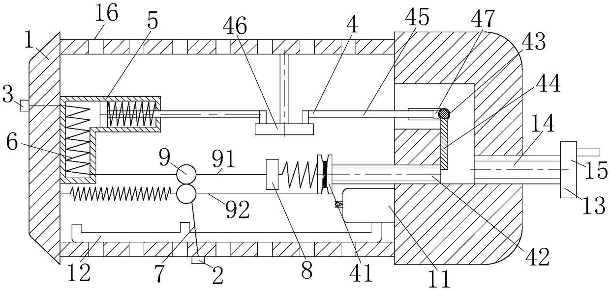
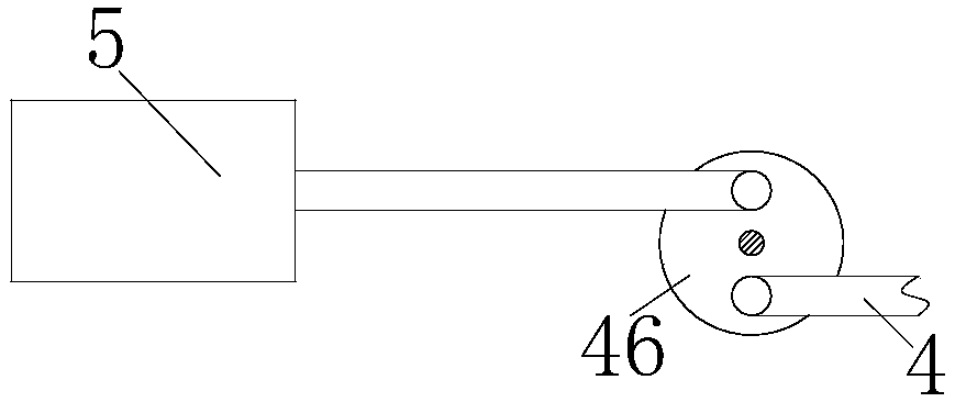
[0016] use Figure 1-Figure 2 The structure of the high voltage protection circuit breaker which concerns on one Embodiment of this invention is demonstrated as follows.

[0017] Such as figure 1 and figure 2As shown, a high voltage protective circuit breaker according to the present invention includes a housing 1, an input terminal 2, an output terminal 3, a circuit breaking module 4, a cylinder 5, an output line 6, an input line 7, a fixing plate 8 and a metal ball 9 The input terminal 2 is arranged on the outer wall of the bottom of the housing 1; the output terminal 3 is arranged on the outer wall of the left side of the housing 1; , the breaking module 4 is used to control the breaking of the circuit breaker; the cylinder 5 is installed on the left inner wall of the housing 1, the cylinder 5 is L-shaped, and mercury is installed in the cylinder on the left side of the cylinder 5, and the mercury expands easily when heated to provide power for the cylinder 5 , the cyli...


PUM


Abstract

The invention belongs to the technical field of circuit breakers, in particular to a high-voltage protection circuit breaker, comprising a housing, an input terminal, an output terminal, a circuit breaker module, an air cylinder, an output wire, an input wire, a fixing plate and a metal ball; An input terminal is arranged on the outer wall of the bottom of the housing; An output terminal is arranged on the left outer wall of the housing; Circuit break module is positioned inside that house, and the circuit breaker module is positioned on the right side of the housing; On the left inner wall ofthe cylinder mounting housing, the cylinder piston rod is connected with the circuit breaker module; The left end of the output line is connected with the output terminal, and the right end of the output line is located in the housing; One end of the input line is connected with the input terminal, and the other end of the input line is located in the housing; The fixing plate is arranged in theshell, and the fixing plate is installed through the front and rear walls of the shell. The number of metal balls is two, the metal balls are arranged up and down, and the metal balls are in contact with each other.

Description

technical field [0001] The invention belongs to the technical field of circuit breakers, in particular to a high-voltage protection circuit breaker. Background technique [0002] Circuit breakers can be used in industrial, commercial and residential applications to protect electrical equipment from overcurrent conditions. The existence of circuit breakers provides a great guarantee for the safety of human electricity use, but the current cut-off speed in existing circuit breakers is often Slow, so that the high current in a short period of time will cause damage to electrical equipment. At the same time, the existing circuit breaker cannot quickly transfer the heat in the circuit breaker to the outside when short-circuited, resulting in a low service life of the circuit breaker. The existing circuit breaker The circuit breaker usually uses a fuse, so that when the high voltage is high, the fuse is blown, thereby ensuring that the circuit breaker cuts off the current. In doin...

Claims


Application Information

Patent Timeline
IPC IPC(8): H01H71/14H01H71/56
CPCH01H71/14H01H71/56H01H2071/147
Inventor 李涵
Owner 李涵
Learn More