Check patentability & draft patents in minutes with Patsnap Eureka AI!

Pulse width modulation converter and its conversion method

A technology of pulse width modulation and conversion method, applied in the direction of pulse duration/width modulation, etc., which can solve the problems of reduced circuit efficiency and power input variation.

Active Publication Date: 2022-08-05
ELITE SEMICON MEMORY TECH INC
View PDF4 Cites 0 Cited by
  • Summary
  • Abstract
  • Description
  • Claims
  • Application Information

AI Technical Summary

Problems solved by technology

In this case, if the pulses of the pair of PWM output signals rise from low level to high level at the same time in a certain cycle, or at a very close time, the power supply must provide a large amount of current instantaneously, so it will Causes sudden drastic changes in the power input, which in turn leads to a reduction in the performance of the overall circuit

Method used


Image

  • Pulse width modulation converter and its conversion method
  • Pulse width modulation converter and its conversion method
  • Pulse width modulation converter and its conversion method

Examples


Embodiment Construction

[0062] The embodiments described below are not intended to limit the invention to only the described environment, application, structure, process or steps. In the drawings, elements not directly related to the present invention are omitted. In the drawings, the size of each element and the ratio between each element are only examples, and are not intended to limit the present invention. Unless otherwise specified, in the following content, the same (or similar) element symbols may correspond to the same (or similar) elements.

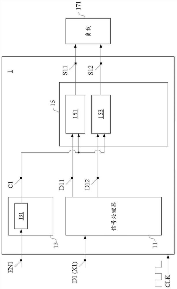
[0063] Certain embodiments of the present invention may be pulse width modulated converters. figure 1 exemplifies the architecture of a PWM converter, however figure 1 What is shown is only to illustrate the embodiments of the present invention, not to limit the present invention. refer to figure 1 , a PWM converter 1 may include a signal processor 11 , a counter 13 , and a comparator 15 . The signal processor 11, the counter 13, and the comparator...


PUM


Abstract

Pulse width modulation converter and its conversion method. In the described embodiment, a first input signal can be converted into a first PWM output signal and a second PWM output signal, wherein the first PWM output signal and the second PWM output signal The output signals are each a center-aligned PWM signal, and in each cycle, the pulse width of the first PWM output signal and the pulse width of the second PWM output signal are different. Thereby, in each cycle, the pulses of the first PWM output signal and the second PWM output signal can be prevented from rising from a low level to a high level at the same time.

Description

technical field [0001] Embodiments of the present invention relate to a converter and a conversion method thereof. More particularly, embodiments of the present invention relate to a pulse width modulation converter and a conversion method thereof. Background technique [0002] Pulse Width Modulation (PWM) is a kind of analog signal or a sampled and encoded analog signal, such as a digital signal after pulse code modulation (Pulse Code Modulation, PCM) on the analog signal. The technique of modulation to generate a pulse output signal, wherein the period of the pulse output signal is generally fixed, and the duty cycle (ie pulse width) of each cycle varies with the amplitude of the analog signal or the corresponding pulse code value and change. [0003] Pulse width modulation techniques are often used in various analog or digital amplifier circuits. Taking a digital amplifier circuit as an example, the PCM signal can generally be converted into a PWM output signal through...

Claims


Application Information

Patent Timeline
Patent Type & Authority Patents(China)
IPC IPC(8): H03K7/08
CPCH03K7/08
Inventor 邱信源曹斯钧林琮富
Owner ELITE SEMICON MEMORY TECH INC
Features
  • R&D
  • Intellectual Property
  • Life Sciences
  • Materials
  • Tech Scout
  • Unparalleled Data Quality
  • Higher Quality Content
  • 60% Fewer Hallucinations
Learn More