A camera control method and a terminal
A control method and camera technology, applied in the communication field, can solve problems such as damage to the contracted area of the FPC, camera failure, etc.
- Summary
- Abstract
- Description
- Claims
- Application Information
AI Technical Summary
Problems solved by technology
Method used
Image
Examples
no. 1 approach
[0048] First Embodiment (corresponding to the switching condition shown in the above-mentioned I)
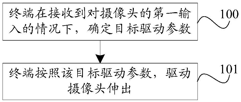
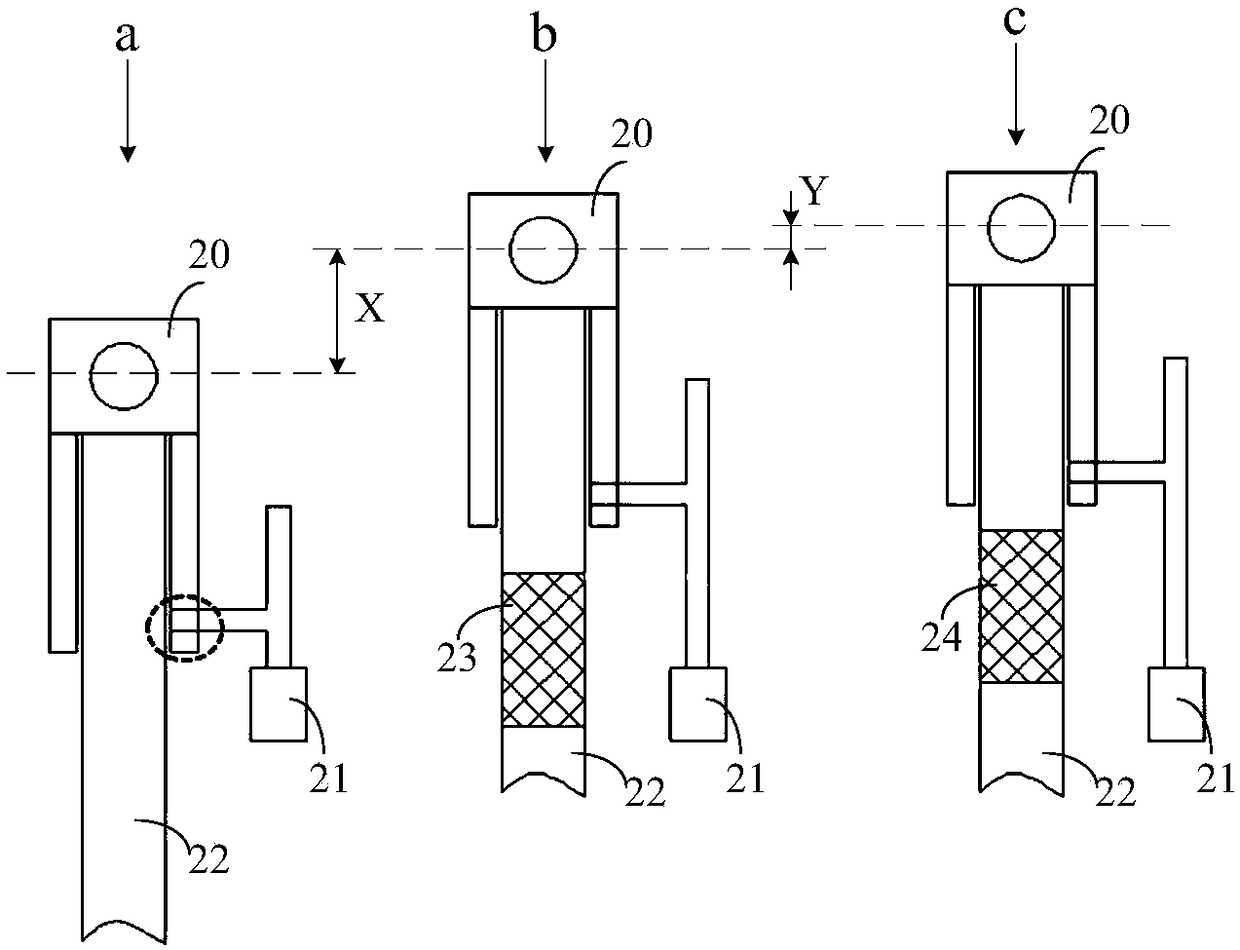
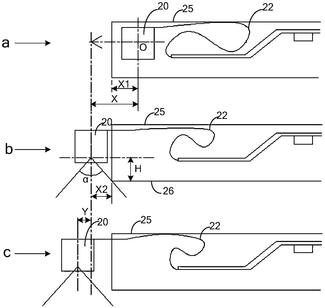
[0049] In the embodiment of the present invention, when the terminal receives the first input to the camera, if the terminal determines that the input triggering the extension of the camera is received, the terminal can determine that the switching condition is met, that is, it can determine to switch from the second switching period to The first switching period (that is, the target switching period), and the terminal can control the driving parameter of the camera to switch from the second driving parameter corresponding to the second switching period to the first driving parameter corresponding to the first switching period (that is, the target driving parameter) , and the terminal can drive the camera to protrude from the terminal according to the first driving parameter, and the maximum distance the camera protrudes is the first maximum protruding stroke (at this time, the p...
no. 2 approach
[0052] Second Embodiment (corresponding to the switching conditions shown in II above)
[0053] In the embodiment of the present invention, when the terminal receives the first input to the camera, if the terminal determines that the target time period is greater than or equal to the preset time threshold, the terminal can determine that the switching condition is met, that is, it can determine that the second switching period Switch to the first switching period (i.e., the target switching period), and the terminal can control the driving parameters of the camera to switch from the second driving parameter corresponding to the second switching period to the first driving parameter corresponding to the first switching period (i.e., the target driving parameter). parameter), and the terminal can drive the camera to protrude from the terminal according to the first driving parameter, and the maximum protruding distance of the camera is the first maximum protruding stroke (at this...
no. 3 approach
[0057] Third Embodiment (corresponding to the switching conditions shown in III above)
[0058] In the embodiment of the present invention, when the terminal receives the first input to the camera, if the terminal determines that the number of telescopic times reaches the preset threshold, the terminal can determine that the switching condition is met, that is, it can determine to switch from the second switching period to the first a switching period (ie, the target switching period), and the terminal can control the driving parameter of the camera to switch from the second driving parameter corresponding to the second switching period to the first driving parameter corresponding to the first switching period (ie, the target driving parameter), And the terminal can drive the camera to protrude from inside the terminal according to the first driving parameter, and the maximum protruding distance of the camera is the first maximum protruding stroke (at this time, the protruding ...
PUM
 Abstract
Description
Claims
Application Information
 - R&D
- Intellectual Property
- Life Sciences
- Materials
- Tech Scout
- Unparalleled Data Quality
- Higher Quality Content
- 60% Fewer Hallucinations
Browse by: Latest US Patents, China's latest patents, Technical Efficacy Thesaurus, Application Domain, Technology Topic, Popular Technical Reports.
© 2025 PatSnap. All rights reserved.Legal|Privacy policy|Modern Slavery Act Transparency Statement|Sitemap|About US| Contact US: help@patsnap.com


