A video mosaic method based on optical flow

A video splicing and optical flow technology, applied in the field of video splicing, can solve the problems of large difference in lighting, jump between frames, affecting visual effects, etc., to save computing time, reduce the amount of calculation, and achieve the effect of accurate optical flow field.

Active Publication Date: 2018-12-11
SHANGHAI JIAO TONG UNIV
View PDF8 Cites 2 Cited by
  • Summary
  • Abstract
  • Description
  • Claims
  • Application Information

AI Technical Summary

Problems solved by technology

With the remarkable results of image stitching, people gradually apply this method to video. For fixed multiple cameras, since the transformation matrix H between videos remains unchanged, it is only necessary to calculate the transformation matrix H at the beginning. This transformation matrix H can be used all the time in the subsequent video frames. This method saves time to a great extent and the splicing speed is faster, but it does not take into account the moving objects appearing in the video, which will affect the optimal image between two frames. Transformation matrix, so it often causes serious blurring effects around moving objects; another video stitching technology will consider calculating the transformation matrix for each frame, so that moving objects can be taken into account, but sometimes the transformation matrix of two adjacent frames changes too much The conference causes jumping between frames and affects the visual effect
[0006] In 2015, Jiang W et al. proposed a spatial-temporal local mapping method to optimize the effect of moving objects. At the same time, the fusion part considered the information of the front and rear frames and proposed 3D suture fusion. This method can effectively optimize moving objects. Stitching effect, but the effect is poor for situations where the difference in illumination between the left and right frames is too large, and there are few feature points that can be extracted from moving objects.

Method used


Image

  • A video mosaic method based on optical flow
  • A video mosaic method based on optical flow

Examples


Embodiment

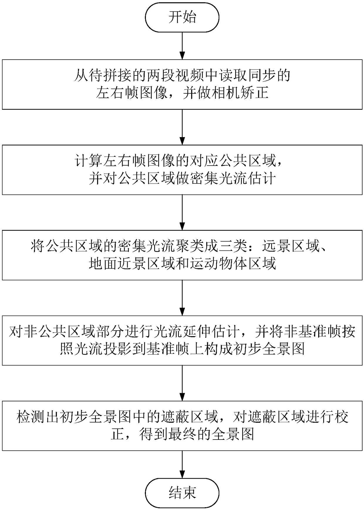
[0034] The present embodiment provides a video splicing method based on optical flow, and the method includes the following steps:

[0035] Step 1: Reading and preprocessing of left and right frame images;

[0036] Step 2: Calculate the corresponding common areas of the left and right frame images, form the common areas of the video to be spliced, and perform dense optical flow estimation on the common areas;

[0037] Step 3: Cluster the dense optical flow in the public area into three categories;

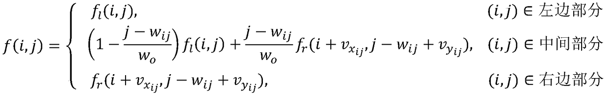
[0038] Step 4: Perform extended estimation of optical flow for non-public areas, and project non-reference frames onto reference frames according to optical flow to form a preliminary panorama;

[0039] Step 5: Detect and correct the masked area of ​​the preliminary panorama to obtain the final panorama;

[0040] Step 6: Go back to Step 1 and read the next pair of left and right frame images.

[0041] Perform steps 1 to 6 again.

[0042] Further, the video to be spliced ​​confo...


PUM


Abstract

The invention discloses a video mosaic method based on optical flow, which comprises the following steps: step S1: reading and preprocessing left and right frame images; 2, calculating the corresponding common area of the left and right frame image, and estimating the dense optical flow of the common area; Step S3: clustering the dense optical flow of the common area into three categories; Step S4, estimating the extension of the optical flow of the non-common area, and projecting the non-reference frame onto the reference frame to form a preliminary panorama according to the optical flow; 5,detecting and correcting that conceal area in the preliminary panorama; Step S6: returning to step S1, and reading the next pair of left and right frame images. The method of the invention aims at thesynchronous monitoring video with fixed camera direction, and can accurately find the corresponding relationship between the common areas of the left and right frame images through the steps, therebyobtaining the panoramic video with good effect, and greatly weakening the blurring and twisting effect on the moving object.

Description

technical field [0001] The present invention relates to the technical field of video stitching, in particular to an optical flow-based video stitching method aimed at optimizing blur and distortion effects of moving objects in public areas. Background technique [0002] With the development of technology, people have higher and higher requirements for video, and one of the most important aspects is the field of view. The field of view of video captured by a single camera is too narrow, and the content that can be presented is relatively small, which cannot meet people's needs. Therefore, people can only adjust the focal length to obtain a wider field of view, but the adjustment of the focal length will cause the picture to become blurred and the resolution to decrease. Later, with the development of the microelectronics industry, people invented wide-angle lenses that can obtain a larger field of view. However, wide-angle lenses are generally expensive and difficult to popu...

Claims


Application Information

Patent Timeline
Patent Type & Authority Applications(China)
IPC IPC(8): H04N7/18H04N5/262
CPCH04N5/2624H04N7/181
Inventor 张小云谢春梅杨华陈立高志勇
Owner SHANGHAI JIAO TONG UNIV
Why Eureka
Try Eureka