Lifting device of lifting table

A lifting device and a lifting table technology, applied in the field of lifting tables, can solve the problems of inconvenient installation, inconvenient installation or disassembly, affecting the structural firmness, reliability and operation stability of a transmission rod assembly, and achieve stable operation, Easy installation, simple and reliable circumferential limit structure

Pending Publication Date: 2018-12-14
LOCTEK ERGONOMIC TECH CORP
View PDF0 Cites 4 Cited by
  • Summary
  • Abstract
  • Description
  • Claims
  • Application Information

AI Technical Summary

Problems solved by technology

[0004] The lifting device of the technical lifting table of the prior art has the following disadvantages: 1. When the telescopic length of the crossbeam needs to be adjusted, the fastening screw must be unscrewed earlier so that the transmission rod can slide freely relative to the transmission tube. Tighten the screws, the operation is inconvenient and relatively cumbersome and time-consuming
2. Since the transmission rod and the transmission tube need to slide, there must be a gap, and the screw fastening will inevitably cause eccentricity, and for strength considerations, the transmission tube is required to have a thicker wall thickness, which increases the material cost
3. Because one end of the transmission rod of the transmission assembly in the prior art is connected to the drive gear, and the other end is connected to the transmission tube, it is very inconvenient to install or disassemble, and the operation is relatively cumbersome and time-consuming
4. The transmission rod assembly is close to one end of the drive mechanism. As time goes by and the frequency of use increases, the fastening structu

Method used


Image

  • Lifting device of lifting table
  • Lifting device of lifting table
  • Lifting device of lifting table

Examples


Embodiment Construction

[0034] The specific embodiments of the present invention will be further described below in conjunction with the accompanying drawings. What needs to be declared here is that the descriptions of these specific implementations are used to help understand the present invention, but are not intended to limit the present invention. In addition, the technical features involved in the various specific embodiments of the present invention described below may be combined with each other as long as they do not constitute conflicts with each other.

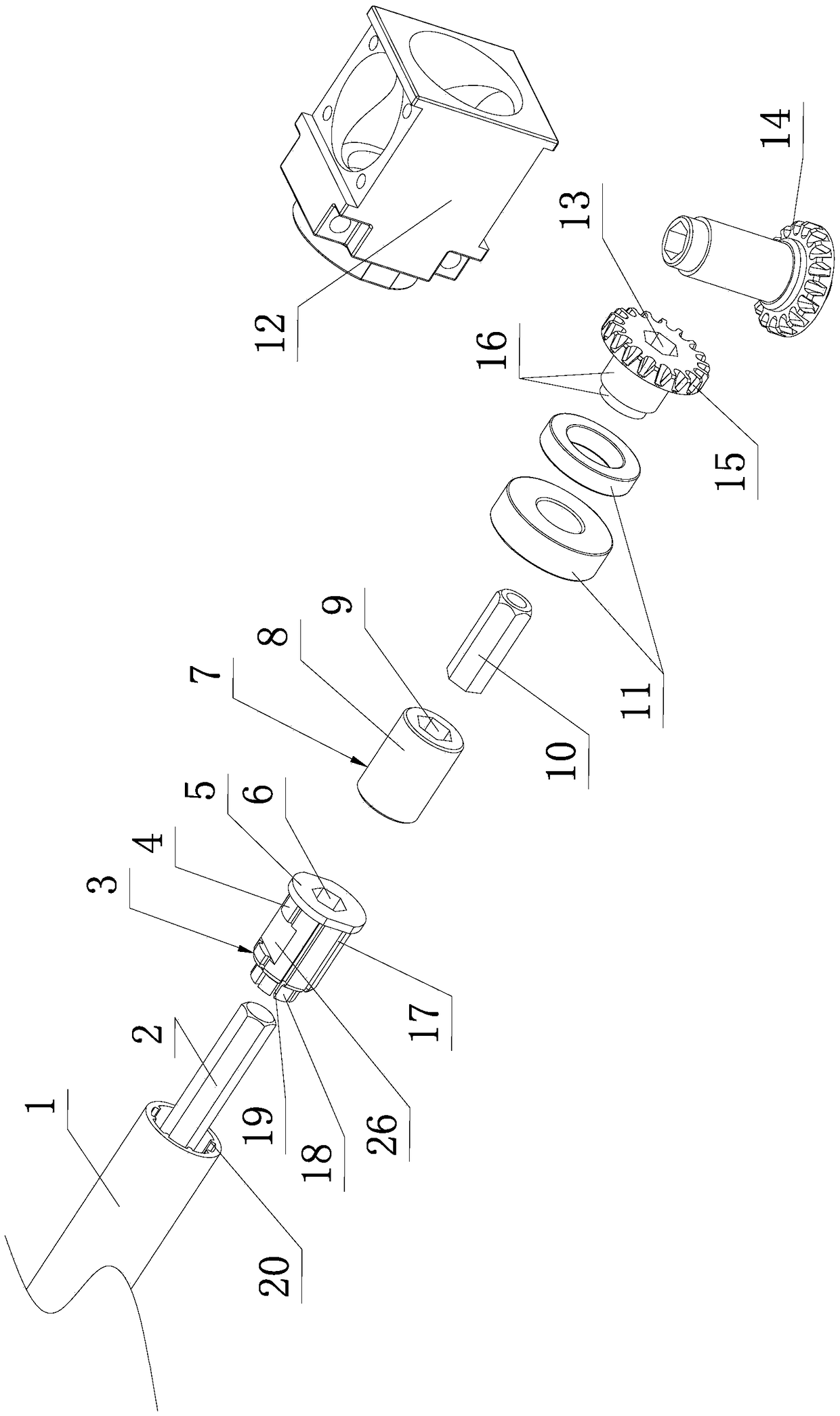
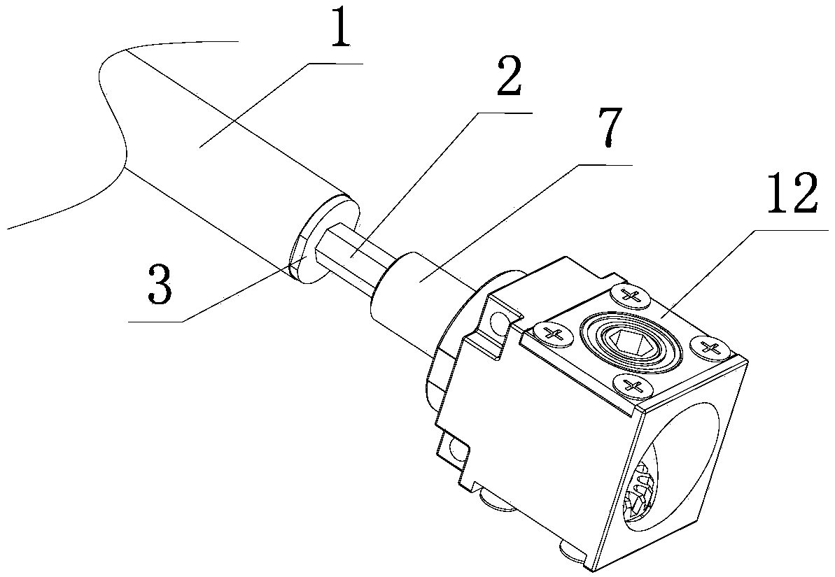
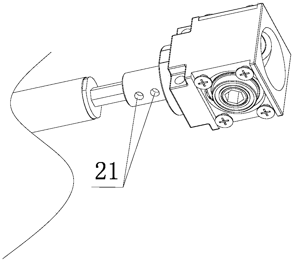
[0035] Such as figure 1 , Figure 5 , Image 6 shown

[0036] The lifting device of the lifting table of the present invention includes a driving mechanism 23 and two gear boxes 12, which are connected with the lifting gear 14 in the gear box 12 and can be rotated positively and negatively under the drive of the lifting gear 14 so as to drive the relative displacement of the inner and outer tubes of the table legs 25. And the screw mand...


PUM


Abstract

The invention discloses a lifting device of a lifting table. The lifting device comprises a drive rod assembly which comprises at least one drive pipe and at least one first drive rod inserted into one end of the drive pipe, wherein the first drive rod is a regular polygon lever. The lifting device also comprises a first connector arranged at the end of the drive pipe. The first connector and thedrive pipe are circumferentially and axially limited. The first drive rod is provided with an adjusting section extending axially into the drive pipe. The central hole of the first connector is a polygonal hole which is slidably matched with the first drive rod so that the first drive rod and the drive pipe are enabled to mutually and automatically expand and contract with expansion and contraction of the crossbeam. The first connector and the first drive rod are provided with an axial limiting structure which prevents the first drive rod from being over-stretched and separated from the drivepipe. The first drive rod and the drive pipe of the drive rod assembly can automatically expand and contract axially with expansion and contraction of the crossbeam.

Description

technical field [0001] The invention relates to the technical field of lifting tables, in particular to a lifting device for lifting tables. Background technique [0002] The lifting device of the prior art lifting table generally includes a driving mechanism and two gear boxes, which are connected with the lifting gear in the gear box and can be rotated positively and negatively under the drive of the lifting gear so as to drive the relative displacement of the inner and outer tubes of the table legs to make the table legs As for the lifting screw lifting mechanism, the specific structure of the driving mechanism can be that the motor shaft or the handle shaft is connected with a worm, and the worm meshes with the worm gear installed on the transmission rod near one end of the driving mechanism of the following transmission rod assembly. [0003] The lifting device also includes a transmission rod assembly connected to the drive mechanism and the gear box, and the transmiss...

Claims


Application Information

Patent Timeline
IPC IPC(8): A47B9/04A47B13/02
CPCA47B9/04A47B13/02A47B2009/046
Inventor 项乐宏蒋领辉魏瑞志
Owner LOCTEK ERGONOMIC TECH CORP
Why Eureka
Try Eureka