Supercharge Your Innovation With Domain-Expert AI Agents!

A device and method for detecting straightness of deep and long holes

A detection device and straightness technology, applied in the direction of measuring devices, optical devices, instruments, etc., can solve the problems of high price, affecting measurement accuracy, complicated operation, etc., and achieve high automation, high measurement accuracy and low measurement cost Effect

Active Publication Date: 2020-09-29
DALIAN UNIV OF TECH
View PDF8 Cites 0 Cited by
  • Summary
  • Abstract
  • Description
  • Claims
  • Application Information

AI Technical Summary

Problems solved by technology

[0005] (1) Chinese Invention Patent Application Publication CN103234486A discloses a non-contact inner hole straightness measurement device and method. The feature of the solution is to use an air-floating cushion to support the mirror to move in the hole, and utilize the precision of the air-floating cushion The accuracy and stability of the workpiece are measured, but the self-centering accuracy of the air cushion is not high, which will cause the axis of the mirror and the inner hole of the workpiece to be measured to be out of axis, which will affect the measurement accuracy
[0006] (2) Chinese utility model patent specification CN203981183U discloses a single laser single PSD storage type deep hole straightness detection device, the feature of the scheme is to use the traction line to pull the self-centering mechanism to make it move in the hole of the workpiece to be measured, The straightness data is measured by the PSD sensor, but its self-centering mechanism will rotate in the hole of the workpiece to be measured, which will affect the measurement accuracy
[0007] Looking at the methods of measuring the straightness of deep holes at home and abroad, if the accuracy needs to be improved, the price is expensive; if the cost needs to be reduced, the accuracy will also decrease, and the operation is complicated

Method used


Image

  • A device and method for detecting straightness of deep and long holes
  • A device and method for detecting straightness of deep and long holes
  • A device and method for detecting straightness of deep and long holes

Examples


specific Embodiment approach

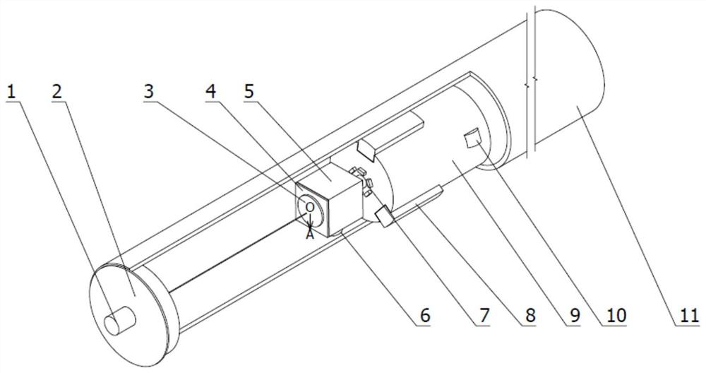
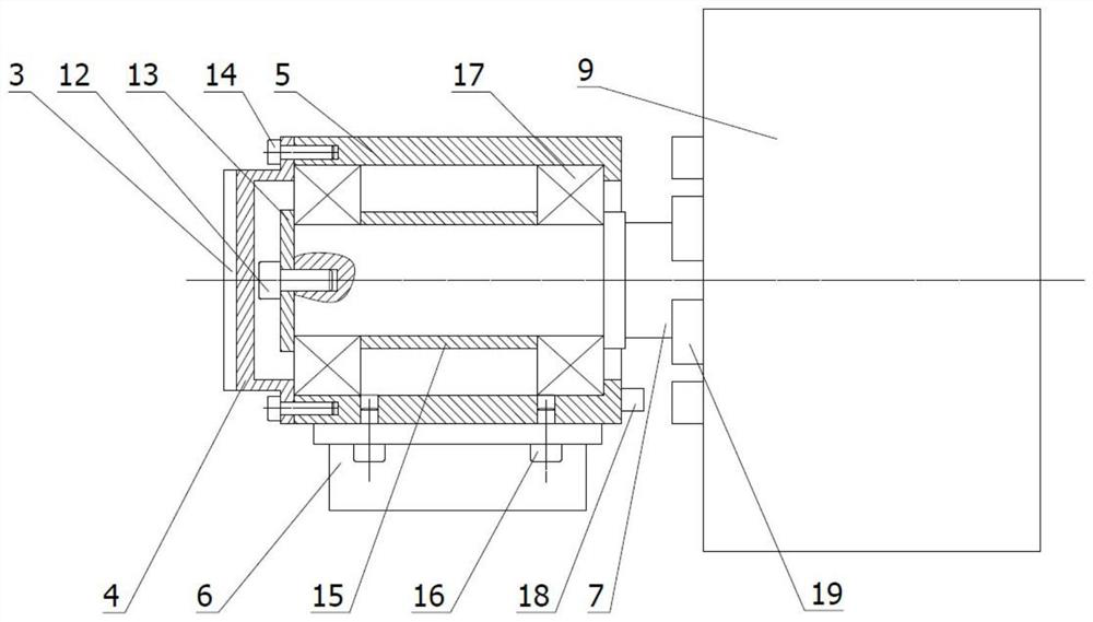
[0030] The specific implementation method is as follows: turn on the power supply, and the self-centering walking mechanism 9 starts to drive the mirror fixing device 5 to move along the axis in the deep hole. The toggle fixing device 5 swings around the central installation axis 7, and when the reading of the inclinometer 6 is 0, the reading of the photoelectric autocollimator 1 is recorded and saved. When the self-centering walking mechanism 9 moves to a certain position, the power is turned off, and the measurement ends. Finally, the computer processes the obtained data and fits a space curve to calculate the error.

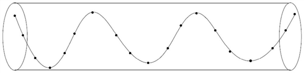
[0031] The present invention also relates to a method for measuring straightness of deep and long holes, such as Figure 5 As shown, using the above-mentioned deep and long hole straightness measuring device includes the following steps:

[0032] (1) Put the measuring mechanism and the self-centering walking mechanism 9 into the deep hole parts 11 in sequenc...


PUM


Abstract

The invention relates to a deep-long hole straightness detection device and method. The device comprises a photoelectric self-collimator, a reflector, a fixed device, an inclinometer and a self-centering walking mechanism, wherein the reflector and the inclinometer are fixed on the fixed device; the fixed device is connected with the self-centering walking mechanism through a central mounting shaft; and the self-centering walking mechanism drives the reflector to move in the deep hole. Light emitted by the photoelectric self-collimator is irradiated on the reflector and is returned to the photoelectric self-collimator for data acquisition, the measured result is subjected to fitting by a computer, and a minimum area method is used for solving. According to the method, spatial coordinates can be collected when the rotation angle of the reflector is zero by means of the inclinometer, so that the influence caused by the non-perpendicularity of the plane of the reflector and the actual axis of the deep hole is eliminated, thereby improving the accuracy of the straightness evaluation result effectively.

Description

technical field [0001] The invention belongs to the technical field of geometric accuracy detection of large-depth-to-diameter ratio hole parts, and in particular relates to a high-precision measuring device and method for straightness of deep and long holes based on a photoelectric autocollimator. Background technique [0002] With the development of modern technology, more and more fields need to use deep and long hole parts, such as oil transportation, electric power, military and so on. The straightness of the inner hole of the large depth-to-diameter ratio directly affects its performance and service life, so it is necessary to check whether the straightness meets the standard before leaving the factory. [0003] The existing straightness detection methods of the inner hole include the contact gauge detection method and the arm method, neither of which can detect the straightness of the inner hole of the deep and long pipe; the non-contact dual-frequency laser interfero...

Claims


Application Information

Patent Timeline
Patent Type & Authority Patents(China)
IPC IPC(8): G01B11/27
CPCG01B11/272
Inventor 康仁科朱祥龙李崎岩董志刚戴恒震张桥杰
Owner DALIAN UNIV OF TECH
Features
  • R&D
  • Intellectual Property
  • Life Sciences
  • Materials
  • Tech Scout
  • Unparalleled Data Quality
  • Higher Quality Content
  • 60% Fewer Hallucinations
Learn More