Quasi-static anti-seismic test loading device with capacity of vertical uniform loading

A technology of uniform loading and seismic test, which is applied in the direction of applying stable tension/pressure to test the strength of materials and the generation of seismic energy.

Active Publication Date: 2018-12-14
WUHAN UNIV OF TECH
View PDF8 Cites 4 Cited by
  • Summary
  • Abstract
  • Description
  • Claims
  • Application Information

AI Technical Summary

Problems solved by technology

Pseudo-static seismic test is the most widely used test method to study the seismic performance of structures or components. In the existing quasi-static seismic tests of structures, vertical uniform loads are usually applied to beam-column and shear wall specimens by using jacks or The distribution beam distribution method of the distribution beam generally realizes two-point or three-point distribution loading through the rolling rod, and there is a large error compared with the uniform distribution loading; secondly, in the test process, the rolling rod presses the horizontal force It is difficult to control the reciprocating rolling in the loading direction without out-of-plane torsion; finally, during the test, under the action of vertical axial force and horizontal force, the lower surface of the rolling rod, the lower steel plate of the rolling rod, and the distribution beam in contact with the rolling rod is easily deformed, Make the roller stick not roll smoothly

Method used


Image

  • Quasi-static anti-seismic test loading device with capacity of vertical uniform loading
  • Quasi-static anti-seismic test loading device with capacity of vertical uniform loading
  • Quasi-static anti-seismic test loading device with capacity of vertical uniform loading

Examples


Embodiment Construction

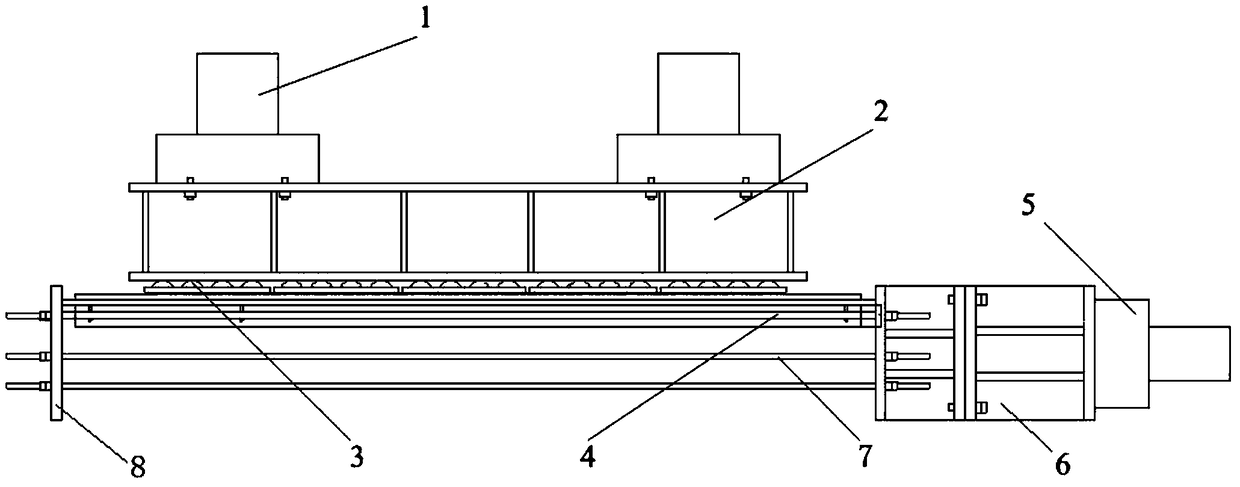
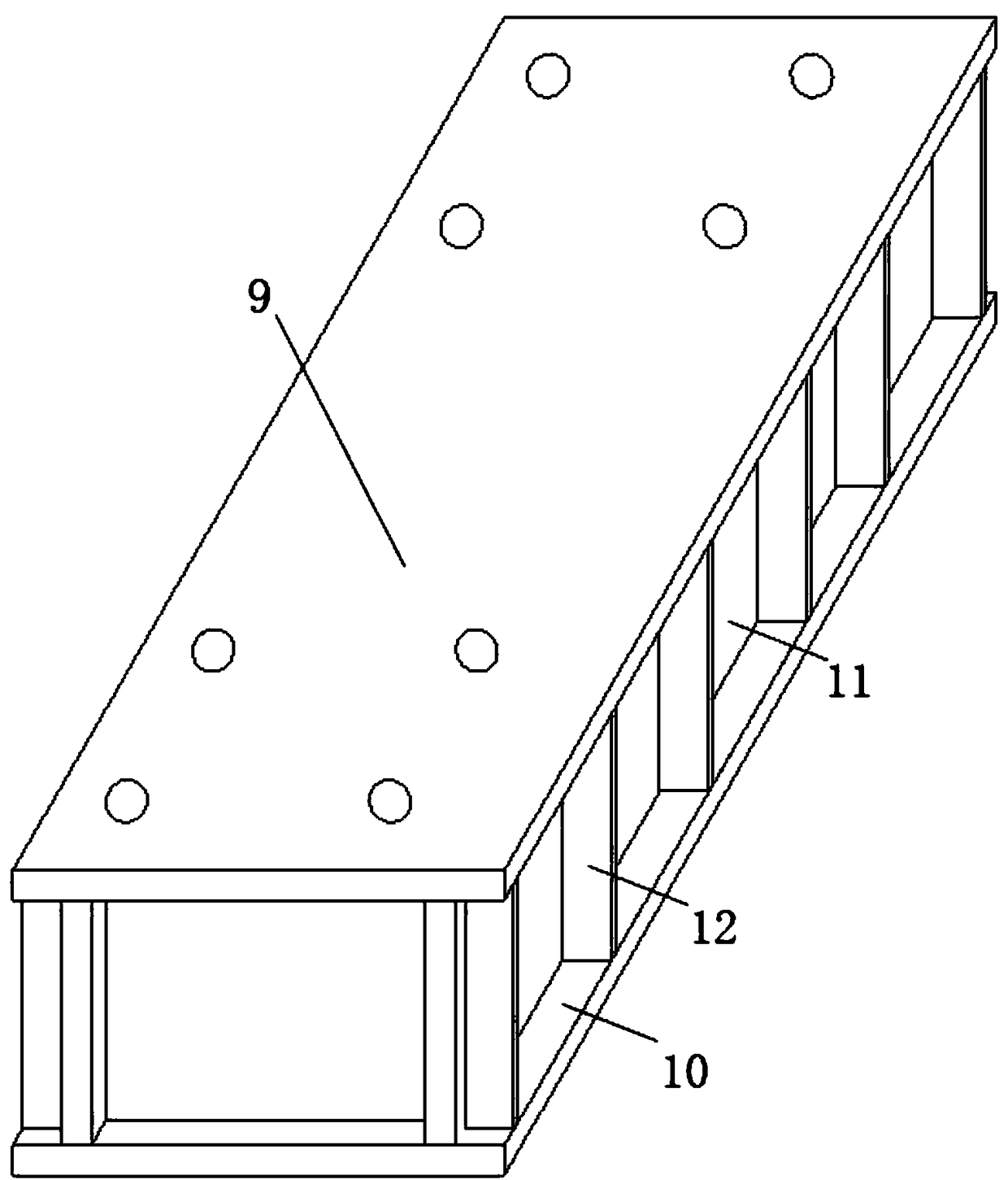
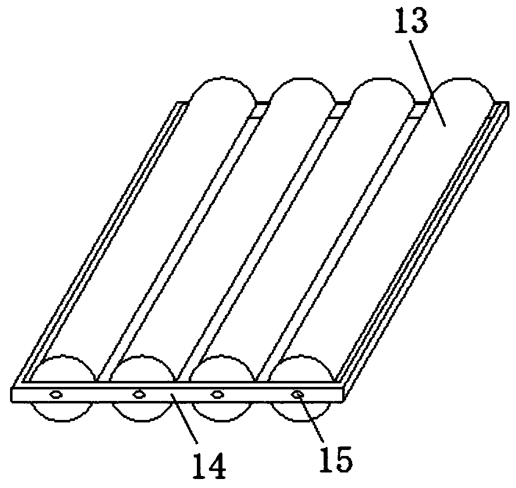
[0022] The present invention will be further described below in conjunction with the accompanying drawings and embodiments.

[0023] like Figure 1 to Figure 5 As shown, a pseudo-static seismic test loading device with uniform vertical loading includes a vertical actuator 1, a distribution beam 2 connected to the vertical actuator 1, a horizontal transverse actuator 5, and a horizontal transverse actuator 5. The connecting beam 6 connected to the actuator 5, the loading beam fixing plate 8, several screw rods 7 passing through the connecting beam 6 and the loading beam fixing plate 8 at the same time, the rolling bar track beam 4 fixed on the upper part of the connecting beam 6 at one end, several groups The rolling rod assembly 3 includes a fixed frame 14 and several rolling rods 13 installed in the fixed frame 14 that roll in the same direction and have constant spacing. Both sides of the top surface of the rolling rod track beam 4 are provided with steel rails 16 and Limit...


PUM

PropertyMeasurementUnit
thicknessaaaaaaaaaa
thicknessaaaaaaaaaa
heightaaaaaaaaaa

Abstract

The invention relates to a quasi-static anti-seismic test loading device with capacity of vertical uniform loading. The device comprises a vertical actuator, a distribution beam connected with the vertical actuator, a horizontal transverse actuator, a connecting beam connected with the horizontal transverse actuator, a loading beam fixing plate, a plurality of screws penetrating the connecting beam and the loading beam fixing plate simultaneously, a rolling bar rail beam with one end fixed to the upper part of the connecting beam and a plurality of rolling bar assemblies, wherein each rollingbar assembly comprises a fixed frame and a plurality of rolling bars which are mounted in the fixed frame and roll in the same direction at constant intervals; steel rails and limiting plates are arranged on two sides of the top surface of the rolling bar rail beam, and anti-separating plates are arranged on two sides of the bottom surface. During operation, the bottom surface of the rolling bar rail beam is placed on the top surface of a loading beam, two side surfaces of the loading beam are located between the anti-separating plates, the plurality of rolling bar assemblies are placed alongthe steel rails and located between the limiting plates, the bottom surface of the distribution beam is pressed on all the rolling bars, and two end surfaces of the loading beam are pressed and fixedby the connecting beam and the loading beam fixing plate through screws. Vertical uniform loading is achieved by the device.

Description

technical field [0001] The invention belongs to the field of civil engineering test equipment, and in particular relates to a pseudo-static anti-seismic test loading device with uniform vertical loading. Background technique [0002] China is located between the world's two major seismic belts—the circum-Pacific seismic belt and the Eurasian seismic belt. It is a country with frequent earthquakes. Every year, earthquakes bring immeasurable losses to our lives and properties. Pseudo-static seismic test is the most widely used test method to study the seismic performance of structures or components. In the existing quasi-static seismic tests of structures, vertical uniform loads are usually applied to beam-column and shear wall specimens with jacks or The distribution beam distribution method of the distribution beam generally realizes two-point or three-point distribution loading through the rolling rod, and there is a large error compared with the uniform distribution loadin...

Claims


Application Information

Patent Timeline
Patent Type & Authority Applications(China)
IPC IPC(8): G01N3/08G01V1/02
CPCG01N3/08G01V1/02
Inventor 谷倩董格张延宾布欣田水
Owner WUHAN UNIV OF TECH
Why Eureka
Try Eureka