Remote monitoring system for optical cable resources

A remote monitoring system and optical cable technology, which is applied in the transmission system, electromagnetic wave transmission system, electrical components, etc., can solve the problems that the data cannot be guaranteed to be 100% accurate, the fiber core occupancy/idle of the optical cable changes frequently, and the work efficiency is affected. Improve the accuracy of data quality, solve the waste of optical cable resources, and improve work efficiency

Inactive Publication Date: 2018-12-14
BEIJING MATARNET TECH
View PDF3 Cites 8 Cited by
  • Summary
  • Abstract
  • Description
  • Claims
  • Application Information

AI Technical Summary

Problems solved by technology

These existing management methods all belong to offline management, and it is difficult to realize real-time update statistics of fiber core occupancy
Coupled with frequent on-site engineering construction, frequent changes in the occupancy / idle status of optical fiber cores, and frequent project information updates and non-updates, etc., resulting in inconsistencies between the idle status of optical fiber cores on site and the data in the management system, management The system cannot guide reproduction, maintenance, etc.
[0003] At present, the main method to solve this problem is to update the data in the management system through artificial on-site census, which is time-consuming and laborious, and it is difficult to guarantee the freshness of the data.
The data of the on-site census is also difficult to guide asset management. The reason is that the on-site census cannot guarantee 100% accuracy of the data, so the method of on-site census can only ensure the accuracy of the data in a short period of time. Can not guarantee
Therefore, there are many problems in the communication industry such as waste of optical cable resources, errors in maintenance resources, and long troubleshooting time, which greatly affect work efficiency and bring a lot of inconvenience.

Method used


Image

  • Remote monitoring system for optical cable resources
  • Remote monitoring system for optical cable resources

Examples


Embodiment Construction

[0027] The specific implementation manners of the present invention will be further described in detail below in conjunction with the accompanying drawings and embodiments. The following examples are used to illustrate the present invention, but are not intended to limit the scope of the present invention.

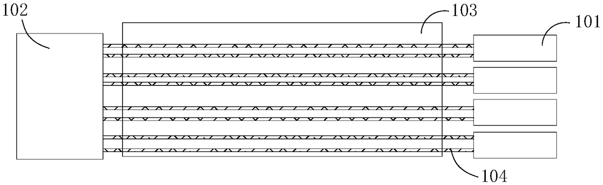
[0028] In order to overcome the above-mentioned problems in the prior art, an embodiment of the present invention provides a remote monitoring system for optical cable resources, figure 1 A schematic structural diagram of a remote monitoring system according to an embodiment of the present invention is shown, as figure 1 As shown, the remote monitoring system includes:

[0029] Several cold connectors 101 arranged at opposite ends of the optical cable, for any fiber core 104 in the optical cable 103, there is a cold connector to connect the fiber core with, and only with, another fiber core to form a loop.

[0030] by figure 1 In the fiber optic cable as an example, fi...


PUM


Abstract

The invention provides a remote monitoring system for optical cable resources, comprising: a plurality of cold connectors arranged at opposite ends of the optical cable; for any fiber core in the optical cable, a cold connector interfaces the fiber core with and only with another fiber core to form a loop; an optical fiber acquisition device provided with an optical fiber cable end is used for receiving configuration information sent by a server to acquire an unused fiber core in the optical fiber cable, sending an optical signal to the unused fiber core, and determining an operation state ofthe optical fiber cable according to the optical signal returned from a loop where the unused fiber core is located. The invention improves that the optical fiber core can be managed only by the artificial on-site survey mode, saves time and labor, improves the accuracy of data quality, solves the problems of waste of optical fiber cable resources, error of maintenance resources, long fault processing time, etc., greatly improves the work efficiency, and brings convenience to daily work.

Description

technical field [0001] The invention relates to the technical field of wireless communication, and more specifically, to a remote monitoring system for optical cable resources. Background technique [0002] In the existing field of optical cable management, the commonly used method is to collect and collect statistics on the spot manually, and enter them into the corresponding management system. These existing management methods belong to offline management, and it is difficult to realize real-time update statistics of fiber core occupancy. Coupled with frequent on-site engineering construction, frequent changes in the occupancy / idle status of optical fiber cores, and frequent project information updates and non-updates, etc., resulting in inconsistencies between the idle status of optical fiber cores on site and the data in the management system, management The system cannot guide reproduction, maintenance, etc. [0003] At present, the main method to solve this problem i...

Claims


Application Information

Patent Timeline
Patent Type & Authority Applications(China)
IPC IPC(8): H04B10/079
Inventor 赵石磊冯少玉
Owner BEIJING MATARNET TECH
Why Eureka
Try Eureka