Electrified railway cantilever supporting device

A technology for electrified railways and support devices, which is applied to overhead lines and other directions, can solve the problems of difficult overall movement, stuck connecting ends of clues and wrist-arm support devices, and deflection of wrist-arm support devices. Good effect, strong overall effect

Pending Publication Date: 2017-07-07
CHINA RAILWAY FIRST SURVEY & DESIGN INST GRP
View PDF5 Cites 3 Cited by
  • Summary
  • Abstract
  • Description
  • Claims
  • Application Information

AI Technical Summary

Problems solved by technology

[0003] Usually, the arm support device used on the electrified railway catenary is composed of flat arm, inclined arm, and arm support. The positioning device and the support device are connected by hook and loop. In areas with large temperature differences between day and night, the overall deflection of the wrist-arm support device is more likely to occur
The traditional wrist-arm support device is connected by a hook and loop, and it is not easy to move as a whole when rotating, and there is a phenomenon that the clues and the connection end of the wrist-arm support device are stuck

Method used


Image

  • Electrified railway cantilever supporting device
  • Electrified railway cantilever supporting device

Examples


Embodiment Construction

[0026] The present invention will be described in detail below in combination with specific embodiments.

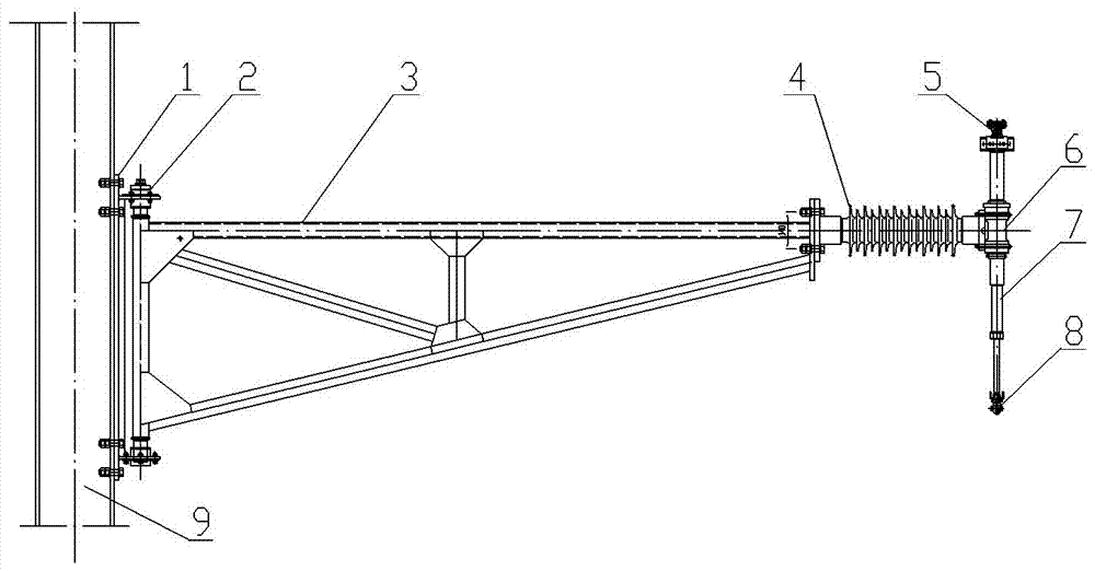
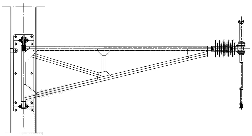
[0027] The present invention relates to an electrified railway arm supporting device, comprising an arm fixed base 1, an arm rotating shaft 2, a triangular truss 3, an arm supporting insulator 4, a positioning rotating shaft 6 and a positioning riser 7.

[0028] The wrist arm fixed base 1 is fixed on the side wall of the pillar 9 by bolts, and the connection method is connected by a reserved hole. The reserved hole adopts three rows of screw holes for step-by-step adjustment, and the channel-type stepless adjustable base can also be used. The connection method is simple and reliable , easy to adjust. A vertical arm rotation shaft 2 is installed on the wrist arm fixed base 1, and the upper and lower ends of the wrist arm rotation shaft 2 are installed on the wrist arm fixed base 1 by the wrist arm rotation shaft shaft seat provided on the wrist arm fixed base 1. The wrist...


PUM


Abstract

The invention relates to an electrified railway cantilever supporting device. In the area with large day and night temperature difference, a contact net extends and retracts along the line direction, overall deflection of the cantilever supporting device easily occurs, overall moving is not liable to conduct at the time of rotating, so that the phenomenon that a wire cable and the connecting end of the cantilever supporting device are blocked exists. A cantilever fixing base is fixed to the side wall of a supporting column. A vertical cantilever rotating shaft is mounted on the cantilever fixing base. One end of a triangular door-shaped truss is mounted on one side of the cantilever fixing base through the cantilever rotating shaft, and the other end of the triangular door-shaped truss is connected with a positioning rotating shaft through a cantilever supporting insulator. The positioning rotating shaft is located in the middle of a positioning vertical pipe and mounted in a bearing mode. A force bearing cable seat is arranged at the upper end of the positioning vertical pipe. A positioning wire clamp is arranged at the lower end of the positioning vertical pipe. According to the electrified railway cantilever supporting device, the overall structure is compact, free rotating is facilitated, unstability out of the plane is not liable to occur, daily work, operation and maintenance are facilitated, and safety is high.

Description

technical field [0001] The invention relates to the technical field of electrified railway catenary, in particular to an electrified railway arm support device. Background technique [0002] The catenary is a device for supplying power to electric locomotives on the electrified railway line. It is mainly composed of contact suspensions, support devices, positioning devices, pillars and foundations. The contact suspension mainly includes catenary cables, contact wires and hanging strings, and its main function is to transmit electric energy to the locomotive. The wrist arm support device is fixed on the pillar for supporting the contact suspension. The positioning device includes a positioning tube and a locator. Its function is to fix the position of the contact wire so that the contact wire is within the range of the running track of the locomotive pantograph slide and transmit the horizontal force of the contact wire to the support. [0003] Usually, the wrist arm suppor...

Claims


Application Information

Patent Timeline
Patent Type & Authority Applications(China)
IPC IPC(8): B60M1/20
CPCB60M1/20
Inventor 田升平王玉环张珹郭凤平金光张晓栋杨艺张学武赵玮王强聂晶鑫
Owner CHINA RAILWAY FIRST SURVEY & DESIGN INST GRP
Why Eureka
Try Eureka