Pull rod connection structure in short-stress path rolling mill

A technology of short stress line and connection structure, applied in the direction of metal rolling stand, metal rolling mill stand, metal rolling, etc., can solve problems such as connection difficulties, and achieve the effect of solving connection difficulties, saving time, and reliable and stable connection

Pending Publication Date: 2018-12-18
中重科技(天津)股份有限公司
View PDF0 Cites 0 Cited by
  • Summary
  • Abstract
  • Description
  • Claims
  • Application Information

AI Technical Summary

Problems solved by technology

[0003] In view of this, the present invention aims to propose a tie rod connection structure in a short stress line rolling mill to solve the problem of difficult connection caused by deviation when the pressing device is connected with the roll system

Method used


Image

  • Pull rod connection structure in short-stress path rolling mill
  • Pull rod connection structure in short-stress path rolling mill
  • Pull rod connection structure in short-stress path rolling mill

Examples


Embodiment 1

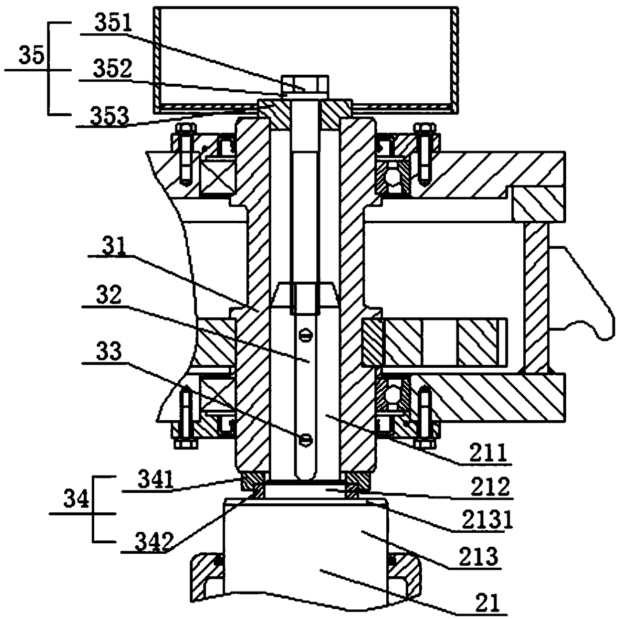
[0026] like figure 1 As shown, a tie rod connection structure 3 in a short stress line rolling mill includes a hollow shaft 31, the shaft head 211 of the tie rod 21 is located in the hollow shaft 31, and the shaft head 211 and the hollow shaft 31 are connected by a key 32, and the shaft head 211 The surface and the inner wall of the hollow shaft 31 are respectively provided with a keyway, and the key 32 is located in the keyway; the upper end of the shaft head 211 is detachably connected in the hollow shaft 31 through a connecting member 35, and the lower end surface of the hollow shaft 31 and the shaft body 213 of the pull rod 21 An adjustment member 34 is installed therebetween, and the adjustment member 34 can be used to adjust the distance between the lower end surface of the hollow shaft 31 and the end surface of the shaft shoulder 2131 of the shaft body 213 . At the same time, the key 32 is fixed in the keyway provided on the shaft head 211 with a screw 33, so that the k...

Embodiment 2

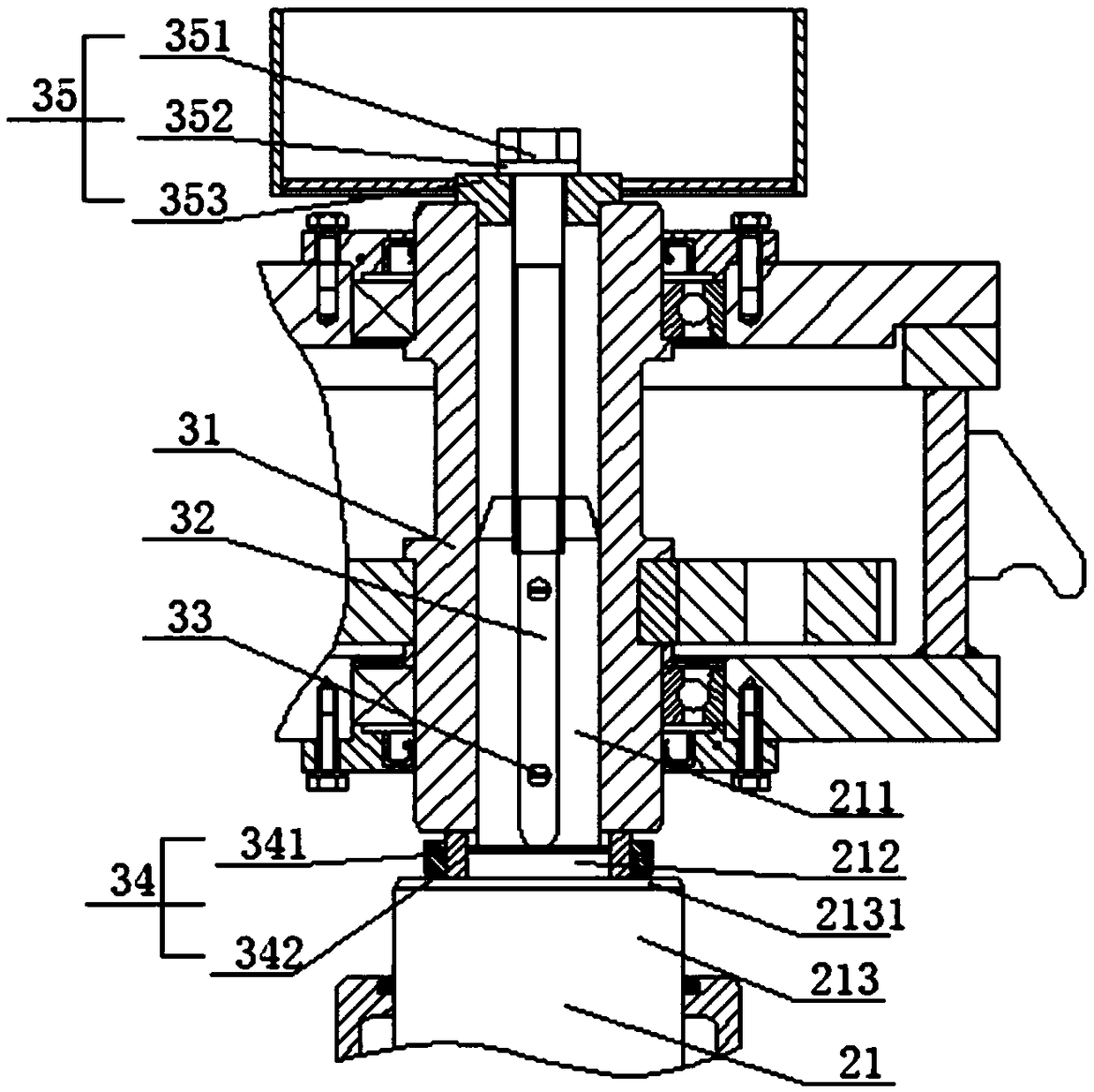
[0031] like figure 2 As shown, a tie rod connection structure 3 in a short stress line rolling mill includes a hollow shaft 31, the shaft head 211 of the tie rod 21 is located in the hollow shaft 31, and the shaft head 211 and the hollow shaft 31 are connected by a key 32, and the shaft head 211 The surface and the inner wall of the hollow shaft 31 are respectively provided with a keyway, and the key 32 is located in the keyway; the upper end of the shaft head 211 is detachably connected in the hollow shaft 31 through a connecting member 35, and the lower end surface of the hollow shaft 31 and the shaft body 213 of the pull rod 21 An adjustment member 34 is installed therebetween, and the adjustment member 34 can be used to adjust the distance between the lower end surface of the hollow shaft 31 and the end surface of the shaft shoulder 2131 of the shaft body 213 . At the same time, the key 32 is fixed in the keyway provided on the shaft head 211 with a screw 33, so that the ...


PUM


Abstract

The invention provides a pull rod connection structure in a short-stress path rolling mill. The pull rod connection structure comprises a hollow shaft. A shaft head of a pull rod is located in the hollow shaft. The shaft head and the hollow shaft are connected through a key. Key grooves are formed in the surface of the shaft head and the inner wall of the hollow shaft correspondingly. The shaft islocated in the key grooves. The upper end of the shaft head is detachably connected in the hollow shaft through a connection component. A regulation component is installed between the lower end faceof the hollow shaft and a shaft body of the pull rod. The regulation component can be used for adjusting the distance between the lower end face of the hollow shaft and the end face of a shaft shoulder of the shaft body. The problem of the connection difficulty caused by installation and machining deviation can be well solved.

Description

technical field [0001] The invention belongs to the technical field of auxiliary equipment for short stress line rolling mills, and in particular relates to a tie rod connection structure in short stress line rolling mills. Background technique [0002] When assembling the short stress line rolling mill, the pressing device is directly installed on the plane composed of multiple tie rods in the roll train. The two boxes of the pressing device are respectively installed on the operation side and the transmission side of the roll train. The tie rods in the roller system are connected. In the actual processing and assembly process, there are processing deviations in the size of each part. The processing deviations of each part accumulate together to make the surface of the multiple tie rods installed with the pressing device inconsistent. Therefore, when When the pressing device is assembled, the boxes on both sides are not on the same plane, and the coupling cannot connect the...

Claims


Application Information

Patent Timeline
Patent Type & Authority Applications(China)
IPC IPC(8): B21B31/04
CPCB21B31/04
Inventor 魏立芬
Owner 中重科技(天津)股份有限公司
Why Eureka
Try Eureka