Solid composite rudder blade high in rigidity and low in weight

A composite material and high-rigidity technology, applied in rudder steering and other directions, can solve the problems of low bending and torsion resistance, corrosion of internal skeleton structure, and high buoyancy of occupied reserves, etc., and achieve the effect of solving the problem of easy corrosion

Active Publication Date: 2016-05-25
NAVAL UNIV OF ENG PLA
View PDF5 Cites 12 Cited by
  • Summary
  • Abstract
  • Description
  • Claims
  • Application Information

AI Technical Summary

Problems solved by technology

Traditional steel rudder blades are mainly steel hollow-core frame structures, which have the following disadvantages: (1) In normal use, seawater can enter and exit freely, and the internal steel skeleton will be soaked in seawater for a long time, and due to the narrow space inside the rudder blade It is impossible to carry out maintenance or maintenance, and the corrosion problem of the internal skeleton structure is very serious; (2) Due to the long-term accumulation of internal sediment, it will also cause the center of gravity of the rudder blade to change, which will affect the handling characteristics; (3) The traditional steel rudder blade skeleton is a steel skeleton

Method used


Image

  • Solid composite rudder blade high in rigidity and low in weight
  • Solid composite rudder blade high in rigidity and low in weight
  • Solid composite rudder blade high in rigidity and low in weight

Examples


Embodiment 1

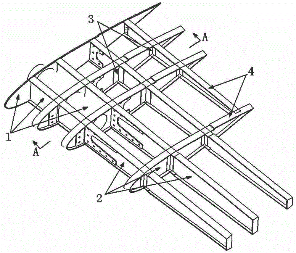
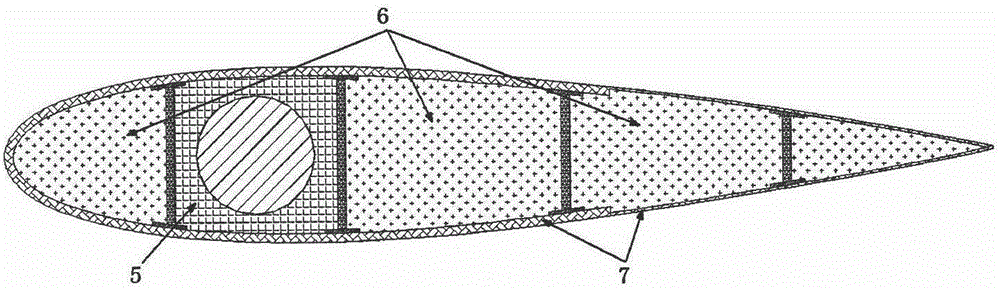
[0025] see figure 1 , figure 2 , image 3 with Figure 4 , the present embodiment is composed of a steel frame 1 in the rudder stock area, a skeleton 2 of composite material, a reinforcement angle 3 , a wing plate of composite material 4 , a damping and / or sound-absorbing material 5 , a buoyancy filling core material 6 and a skin 7 of composite material.

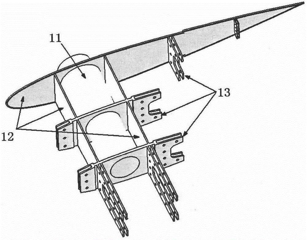
[0026] The steel frame 1 in the rudder stock area is made of No. 45 high-strength steel. The end of the rudder stock is welded with a whole piece of steel end plate, and the composite material skin 7 is terminated at the outer edge of the end plate, which can be connected watertight by screws or embedded The watertight connection structure is terminated; the steel frame 1 in the rudder stock area is composed of a rudder stock 11, a steel skeleton 12 and steel connectors 13, and the number of steel connectors 13 is 4 in the chord direction and 4 in the span direction; the rudder stock The surrounding is filled with dampin...

Embodiment 2

[0033] The structure of embodiment 2 is basically the same as embodiment 1, the difference is:

[0034] Such as Figure 5 As shown, blind holes 15 are provided at the end of the rudder stock 11 of the steel frame 1 in the rudder stock area, lightening holes 14 are provided on the steel frame 12, and lightweight foam materials are filled around the rudder stock 11 and in the blind holes at the ends to To further reduce the structural weight, the number of steel connectors 13 is 6 in the chord direction and 3 in the span direction. For the specific structure, see Figure 4 .

[0035] Such as Image 6As shown, the composite material skeleton 2 is composed of three cross ribs 22 and four chord ribs 21. The numbering of the ribs 22 from the leading edge to the trailing edge is sequentially numbered 1 to 3, and their thicknesses are sequentially 20mm, 20mm, 20mm, the chord ribs 21 are numbered successively from the rudder stock to the rudder shed as chord 1 to chord 4, and their ...


PUM

PropertyMeasurementUnit
Thicknessaaaaaaaaaa

Abstract

The invention discloses a suspension rudder blade applied to a water surface vehicle or an underwater vehicle. The rubber blade comprises a rudder stock area steel frame (1), a composite framework (2), a damping and/or sound-absorbing material (5), buoyancy filling core materials (6) and composite skin (7), and the rudder stock area steel frame (1) is fixedly connected with the composite framework (2), so that an overall framework structure of the rudder blade is formed, and the surface layer of the overall framework structure of the rudder blade is coated with the composite skin (7), so that a watertight structure is formed, gaps between the overall framework structure of the rudder blade and the composite skin (7) are filled with the buoyancy filling core materials (6), and the space around a rudder stock of the rudder stock area steel frame (1) is filled with the damping and/or sound-absorbing material (5). The solid composite rudder blade high in rigidity and low in weight has the advantages of being high in bending resistance/ torsional resistance, resistant to corrosion, low in underwater weight and low in noise.

Description

technical field [0001] The invention relates to rudder blades used for water surface or underwater vehicles, in particular to a rudder blade of high rigidity and light weight solid composite material for ships. Background technique [0002] As a control surface, rudder blades are usually installed at the tail of the aircraft (underwater vehicles can also be installed at the head) and immersed in water. When the aircraft is sailing, the rudder force is generated by turning the rudder blades to control the course. Traditional steel rudder blades are mainly steel hollow-core frame structures, which have the following disadvantages: (1) In normal use, seawater can enter and exit freely, and the internal steel skeleton will be soaked in seawater for a long time, and due to the narrow space inside the rudder blade It is impossible to carry out maintenance or maintenance, and the corrosion problem of the internal skeleton structure is very serious; (2) Due to the long-term accumula...

Claims


Application Information

Patent Timeline
IPC IPC(8): B63H25/38
CPCB63H25/38
Inventor 梅志远李华东刘令陈国涛
Owner NAVAL UNIV OF ENG PLA
Why Eureka
Try Eureka