Substrate mounting for organic, dielectric, optical film

a dielectric and organic technology, applied in the field of substrate mounting for organic dielectric and optical films, can solve the problems of inconvenient manufacturing, inability to meet the requirements of optical coupling films, and inability to achieve the effect of improving optical transmission

Inactive Publication Date: 2005-10-04
GENTEX CORP
View PDF17 Cites 148 Cited by
  • Summary
  • Abstract
  • Description
  • Claims
  • Application Information

AI Technical Summary

Benefits of technology

[0009]It is a further object of the invention to provide industrial processes for fusing thermoplastic substrates to dielectric films without delamination while improving optical transmission at the film's refractive boundary.

Problems solved by technology

By creating so-called quarter wave stacks, certain wavelengths can be destructively interfered via Bragg diffraction.
However, numerous disadvantages exist with these constructs as follows: the labor, materials and equipment costs for manufacturing are prohibitive; the mechanical coupling of metal oxide layers onto polymeric substrates is subject to delamination from flexural stress; the differing rates of thermal expansion between the metal oxides and the polymeric substrate can also cause delamination.
While this allows the film to be economically manufactured, a problem exists in optically coupling the film to other components, for example, an optical thermoplastic substrate.
Because the delicate film is highly susceptible to delamination, melting, burning or having its desirable transmission properties altered, previous attempts to mount the film have been limited to adhesion via optical fluids or optical adhesives.
While these methods are adequate, they severely reduce the film's high transmission characteristics, by providing refractive boundaries from film-to-adhesive and from adhesive-to-substrate.

Method used


Image

  • Substrate mounting for organic, dielectric, optical film
  • Substrate mounting for organic, dielectric, optical film
  • Substrate mounting for organic, dielectric, optical film

Examples


Embodiment Construction

[0025]In U.S. Pat. No. 5,882,774 films are stacked together to improve transmission spectra. For example, a pair of 204-layer polarizers made from alternating layers of PEN and coPEN are laminated together. More specifically, the outer coPEN layer on one polarizer is laminated to the outer coPEN layer of the other polarizer. In this instance, an optical adhesive is used: wherein the only important property of the adhesive is that it possesses a refractive index as close to the coPEN as possible. In other instances a relatively thick skin layer is formed on the exterior surface of the film. In the above example, the skin layer would be formed from PEN or coPEN. In any event, the skin layer is made from one of the polymers used in the film.

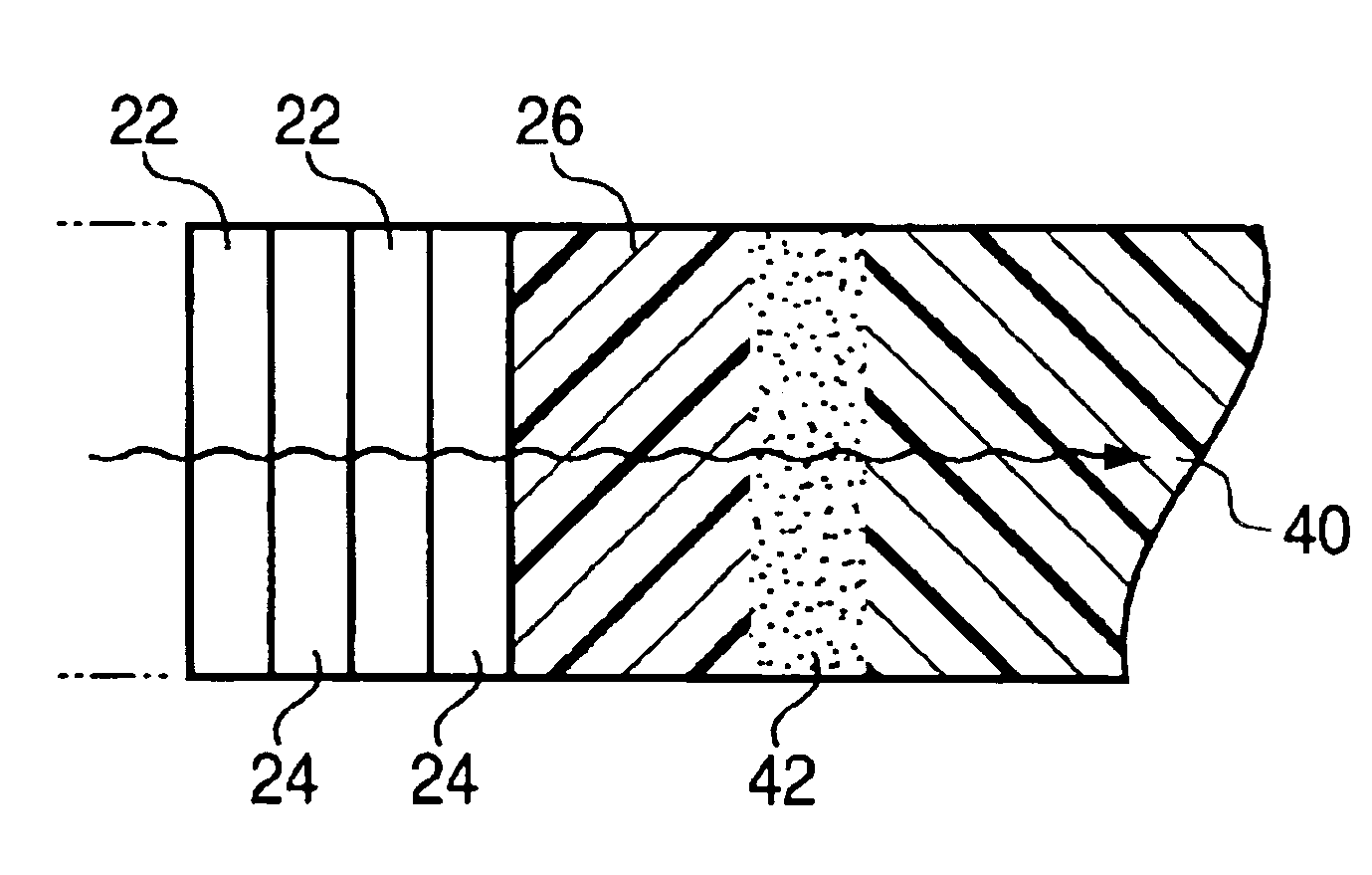
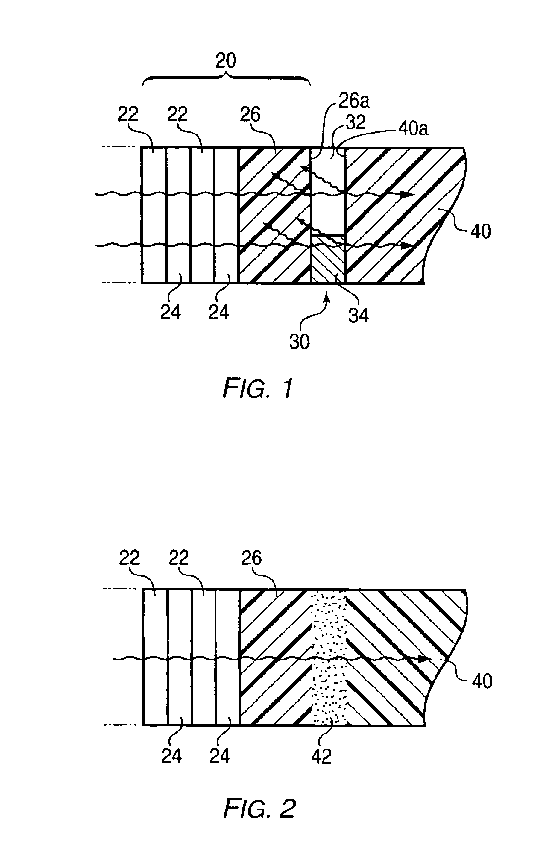
[0026]As can be seen in FIG. 1, a problem exists in layering a film 20 onto a substrate 40. For example, coupling a film 20 made from alternating layers 22, 24 of PEN and coPEN (or PEN and PMMA) to a substrate 40 having different mechanical, chemica...


PUM

PropertyMeasurementUnit
wavelengthsaaaaaaaaaa
visible wavelengthsaaaaaaaaaa
integrated transmission propertiesaaaaaaaaaa

Abstract

A method for optically coupling a thermoplastic material to an outer surface layer of an organic, dielectric, optical film and the resulting optical filter. Initially, a dielectric film is selected that includes (i) repeating optical layers of at least two polymers having different refractive indexes from each other, (ii) an exterior film surface, (iii) a refractive boundary along the exterior film surface, and (iv) a delamination threshold based on total thermal energy delivered to the film. A thermoplastic material which is miscible with the exterior film surface is fused to the refractive boundary with thermal energy below the delamination threshold to form a polydisperse region having a higher optical transmission than the refractive boundary. Add-on filters in the form of hardcoat layers, anti-reflection layers, holograms, metal dielectric stacks and combinations of these may be combined with the thermoplastic-film construct.

Description

RELATED APPLICATION INFORMATION[0001]This application is a Divisional application of U.S. patent application Ser. No. 09 / 955,903 filed on Sep. 19, 2001, now U.S. Pat. No. 6,676,859.BACKGROUND OF THE INVENTION[0002]1. Field of the Invention[0003]The invention relates to methods for mounting thermoplastic substrates to organic, dielectric films and the resulting optical filters. More particularly, it relates to methodologies for fusing, through a variety of industrial processes, thermoplastic substrates to dielectric films without delamination while improving optical transmission at the film's refractive boundary.[0004]2. Description of the Prior Art[0005]Dielectric stacks have previously been constructed by sputtering layers of inorganic (metal) oxides onto polymeric substrates. The layers alternate between high and low indices of refraction, whereby incoming light encounters a partial mirror at each new layer. By creating so-called quarter wave stacks, certain wavelengths can be des...

Claims


Application Information

Patent Timeline
Patent Type & Authority Patents(United States)
IPC IPC(8): G02B5/28B05D7/02B05D7/24B29C45/14G02B1/10G02B1/11
CPCB29C45/14311B29C47/0021B29C47/025B29C66/1122B29C66/341B29C66/73115G02B5/287B29C65/48B29C66/41B29C66/545B29C45/14811Y10T428/24942B29C65/1616B29C65/1635B29C65/1683B29C2045/14319B29C2947/92647B29C2947/92704B29C2947/92742B29C2947/92752B29K2069/00B29K2101/12B29K2105/005B29K2105/256B29K2995/0006B29K2995/0026B29L2011/0066B29C65/1654B29C65/1674B29C66/45B29C66/71B29C66/73117B29C66/73343B29C48/08B29C48/154B29C2948/92647B29C2948/92704B29C2948/92742B29C2948/92752Y10T428/31504Y10T428/31678Y10T428/31681Y10T428/31692Y10T428/31786Y10T428/31797B29K2067/00B29K2033/12B05D5/06
Inventor HARTLEY, SCOTT M.SALLAVANTI, ROBERT A.
Owner GENTEX CORP
Why Eureka
Try Eureka