
Electrostatic chuck

a technology of electrostatic chuck and substrate, which is applied in the direction of electrostatic holding device, basic electric elements, electric apparatus, etc., can solve the problems of substrate distorted, difficult control of contact amount between substrate and protruding protruding, and more restrictive allowable particulate contamination process specifications

Active Publication Date: 2009-11-19
ENTEGRIS INC
View PDF48 Cites 157 Cited by
  • Summary
  • Abstract
  • Description
  • Claims
  • Application Information

AI Technical Summary

Benefits of technology

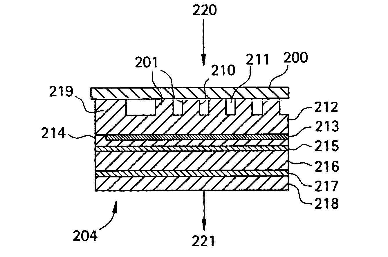
[0008]In other related embodiments, the protrusions may be formed from at least one low stress material, which may comprise at least one of an amorphous dielectric material and a polycrystalline dielectric material. The protrusions may comprise a dielectric material having a resistivity greater than about 1012 ohm-cm. The dielectric material may included at least one of silicon, an alloy of silicon with at least one other element, silicon carbide and non-stoichiometric silicon carbide. Further, the protrusions may comprise a dielectric material including at least one of alumina and aluminum nitride. The protrusions may comprise a dielectric material such that a Johnsen-Rahbek force or partial hybrid Johnsen-Rahbek force does not act on the substrate during the electrostatic clamping. Also, the protrusions may comprise a compliant dielectric material; and may comprise a dielectric material having a resistivity such that the substrate is retained upon the electrostatic chuck via the Johnsen-Rahbek effect during the electrostatic clamping.

Problems solved by technology

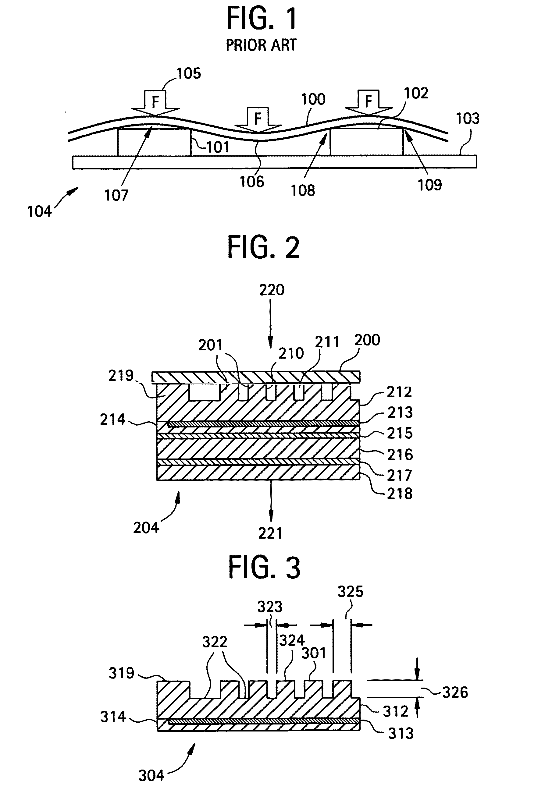
However, controlling the amount of contact between the substrate and the protrusions can be difficult.
In microelectronics production, as semiconductor and memory device geometries become progressively smaller and the sizes of wafers, flat screen displays, reticles and other processed substrates become progressively larger, the allowable particulate contamination process specifications become more restrictive.
If there are excessive temperature variations across the substrate surface due to poor and / or non-uniform heat transfer, the substrate can become distorted and process chemistry can be affected.
Since the characteristics of the contact surface vary from substrate to substrate, and since the characteristics of the contact surface can change over time, accurately controlling contact heat conductance between the electrostatic chuck and substrate is difficult.

Method used


Image

  • Electrostatic chuck
  • Electrostatic chuck
  • Electrostatic chuck

Examples


example 1

[0071]This example illustrates calculated forces for a trigonal pattern of 6 micron high bumps or protrusions, formed on the surface of an electrostatic chuck in accordance with an embodiment of the invention. As shown in the embodiment of FIG. 8, on example includes protrusions 801 that feature a 4 millimeter center to center spacing 827 and a diameter 828 of 0.75 millimeters. In the embodiment of FIG. 8, the protrusions 801 may be made from 10 micron thick SiC vapor deposited from Si and C sources by PECVD on an alumina dielectric layer. The SiC has a low stress. The SiC layer may be etched by reactive ion etching through a 30 micron photomask to form the protrusions. Gas seal rings may be formed around the perimeter of the electrostatic chuck, and around the lift and ground pin holes of the electrostatic chuck. Gas ports for adding and removing a gas, such as helium or hydrogen or another fluid for gas heat transfer may be formed in the chuck.

[0072]FIG. 6 is a graph of calculated...

example 2

[0074]This example describes a trigonal pattern of protrusions that was formed on the surface of an electrostatic chuck, with 8 millimeter center to center spacing between protrusions in accordance with an embodiment of the invention. The diameter of the protrusions was 0.5 millimeters. The protrusions on the platen of the electrostatic chuck were divided into three sections and made from different materials (SiC, a non-stoichiometric SiC deficient in carbon, and an Si section). The individual sections were made by PECVD of suitable precursor gases deposited on an alumina dielectric layer. The sections were etched by reactive ion etching through a 30 micron photomask to form the protrusions. Gas seal rings may be formed around the perimeter of the electrostatic chuck and around the lift and ground pin holes of the electrostatic chuck. Gas ports for adding and removing a gas, such as helium or hydrogen or another fluid for gas heat transfer, may be formed in the chuck.

[0075]FIGS. 9A ...


PUM


Abstract

In accordance with an embodiment of the invention, there is provided an electrostatic chuck comprising an electrode, and a surface layer activated by a voltage in the electrode to form an electric charge to electrostatically clamp a substrate to the electrostatic chuck. The surface layer includes a plurality of protrusions extending to a height above portions of the surface layer surrounding the protrusions to support the substrate upon the protrusions during electrostatic clamping of the substrate. The protrusions are substantially equally spaced across the surface layer as measured by a center to center distance between pairs of neighboring protrusions.

Description

RELATED APPLICATIONS[0001]This application claims the benefit of U.S. Provisional Application No. 61 / 054,259, entitled “Electrostatic Chuck,” filed on May 19, 2008, and U.S. Provisional Application No. 61 / 094,700, entitled “Electrostatic Chuck,” filed on Sep. 5, 2008. The entire teachings of these applications are hereby incorporated herein by reference.BACKGROUND OF THE INVENTION[0002]An electrostatic chuck holds and supports a substrate during a manufacturing process and also removes heat from the substrate without mechanically clamping the substrate. During use of an electrostatic chuck, the back side of a substrate, such as a semiconductor wafer, is held to the face of the electrostatic chuck by an electrostatic force. The substrate is separated from one or more electrodes in the face of the electrostatic chuck by a surface layer of material that covers the electrode. In a Coulombic chuck, the surface layer is electrically insulating, while in a Johnsen-Rahbek electrostatic chuc...

Claims


Application Information

Patent Timeline
Patent Type & Authority Applications(United States)
IPC IPC(8): H01L21/683H01L21/306
CPCH01L21/6831H02N13/00H01L21/6875H01L21/6833
Inventor COOKE, RICHARD A.
Owner ENTEGRIS INC
Learn More