Supercharge Your Innovation With Domain-Expert AI Agents!

Squeeze riveter

A technology of riveting machine and riveting head, which is applied in the field of plate riveting, can solve the problems of cumbersome and inconvenient operation and low processing efficiency, and achieve the effect of convenient and fast operation and improved processing efficiency

Active Publication Date: 2018-12-18
上海亚荣电梯设备制造有限公司
View PDF7 Cites 8 Cited by
  • Summary
  • Abstract
  • Description
  • Claims
  • Application Information

AI Technical Summary

Problems solved by technology

[0004] When the above-mentioned mobile riveting machine is used to rivet the bottom plate 1 and the top, workers need to align the mounting holes 12 of the top plate 11 and the bottom plate 1, and then rivet the four mounting holes 12 in four times, which is cumbersome and inconvenient to operate. and low processing efficiency

Method used


Image

  • Squeeze riveter
  • Squeeze riveter
  • Squeeze riveter

Examples


Embodiment

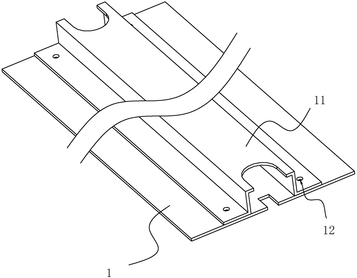
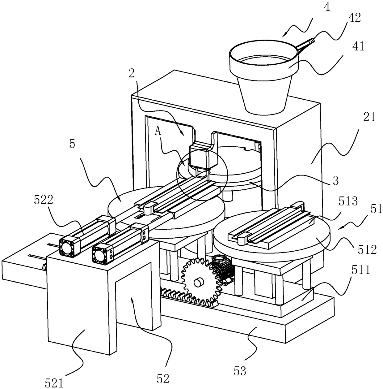
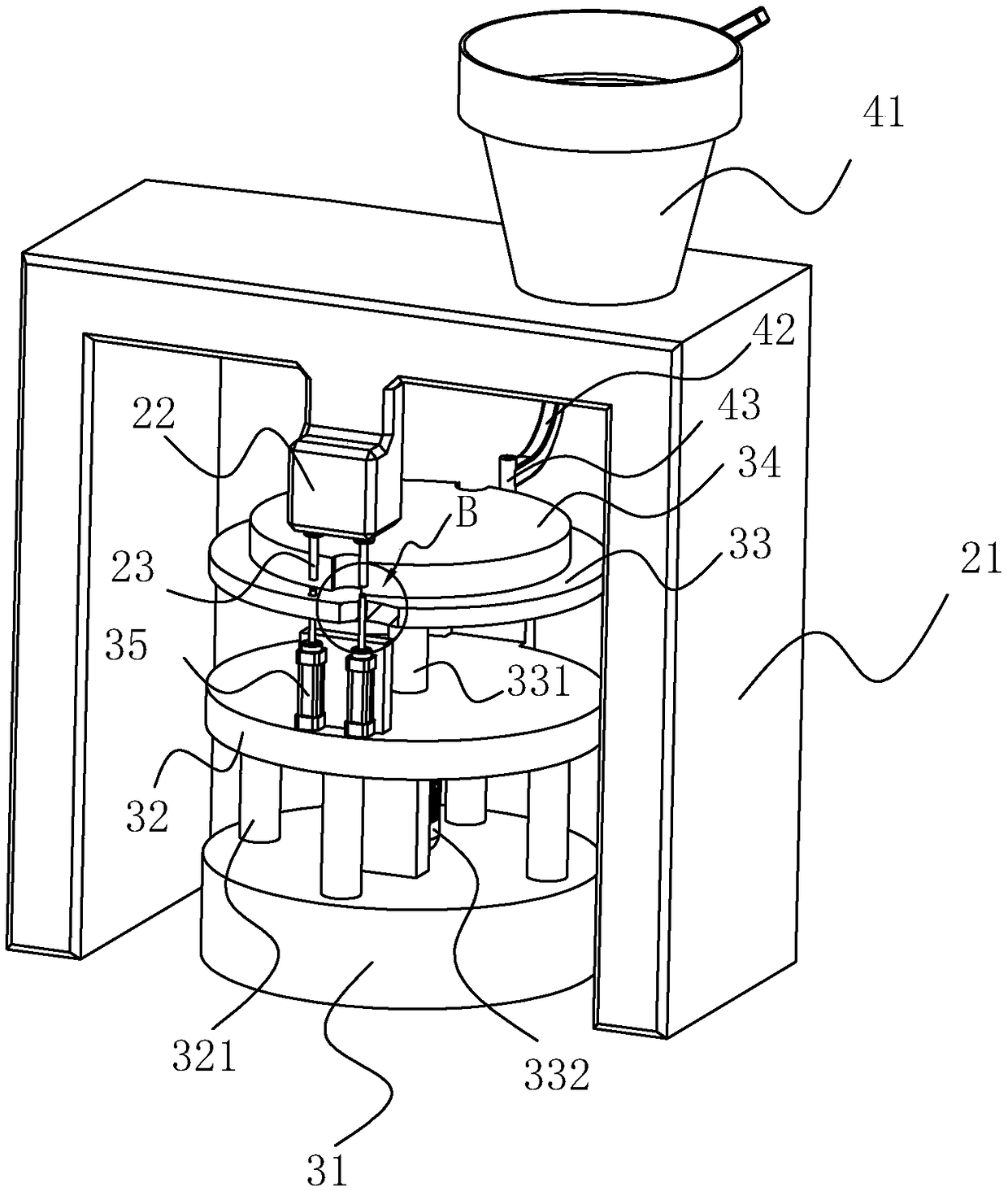
[0046] Embodiment: a kind of pressure riveting machine, is used for carrying out pressure riveting to top plate 11 and bottom plate 1, see attached figure 1 , including a riveting mechanism 2, a rivet rotating mechanism 3 arranged at the bottom of the riveting mechanism 2, a nailing mechanism 4 for conveying rivets into the rivet rotating mechanism 3, and a riveting mechanism arranged on one side of the riveting mechanism 2 for Plate riveting device 5 for rotating and riveting; the plate riveting device 5 includes a plate rotating mechanism 51 arranged on one side of the riveting mechanism 2 for fixedly rotating the plate, and a plate rotating mechanism 51 arranged on the other side of the plate rotating mechanism 51 relative to the riveting mechanism 2. The sheet feeding mechanism 52 on the side is used to push the sheet into the riveting mechanism 2 and lowers it, and the support seat 53 provided at the bottom of the sheet rotating mechanism 51 is used to support the sheet ro...


PUM


Abstract

The invention discloses a squeeze riveter and relates to the field of plate pressing riveting. The problems that in the prior art, in the process of carrying out pressing riveting on a top plate and abottom plate, pressing riveting needs to be repeatedly carried out four times, operation is tedious and not convenient, and the machining efficiency is low are solved. According to the technical scheme, the squeeze riveter is characterized by comprising a supporting frame, a pneumatic base arranged on one side of the top of the supporting frame, two pressing riveting heads which are arranged below the pneumatic base and are driven by the pneumatic base to move up and down, a rivet rotating mechanism arranged on the bottom of the supporting frame, a plate rotating mechanism which is arranged on one side of the pressing riveting mechanism and is used for carrying out fixing rotation on the plate and a plate feeding mechanism which is arranged on the other side, opposite to the plate rotating mechanism, of the pressing riveting mechanism and used for pushing the plate to the part below the pressing riveting mechanism. A worker puts the top plate and the bottom plate to the plate rotatingmechanism, the squeeze riveter carries out pressing riveting on the top plate and the bottom plate at twice, operation is convenient, and the machining efficiency is improved.

Description

technical field [0001] The invention relates to the field of plate pressure riveting, more specifically, it relates to a pressure riveting machine. Background technique [0002] During the process of plate processing and assembly, many plates need to be riveted, see the attached figure 1 , the bottom plate 1 and the top plate 11 arranged above the bottom plate 1; the bottom plate 1 is arranged in a rectangular shape, the top plate 11 is arranged in an Ω shape, the length of the top plate 11 is equal to the length of the bottom plate 1, and the bottom sides of the bottom of the top plate 11 are provided with a The mounting holes 12 at the two ends of the bottom edge are located in the middle of the width direction of the bottom plate 1 when the top plate 11 is installed. Four mounting holes 12 are also provided on the bottom plate 1, and the mounting holes 12 on the bottom plate 1 are connected with the mounting holes 12 on the top plate 11. One to one correspondence. When ...

Claims


Application Information

Patent Timeline
IPC IPC(8): B21J15/10B21J15/32B21J15/38
CPCB21J15/10B21J15/32B21J15/38
Inventor 王继荣张民
Owner 上海亚荣电梯设备制造有限公司
Features
  • R&D
  • Intellectual Property
  • Life Sciences
  • Materials
  • Tech Scout
  • Unparalleled Data Quality
  • Higher Quality Content
  • 60% Fewer Hallucinations
Learn More