Pressure maintaining and increasing hinge and welding machine thereof

A hinge and hinge technology, which is applied in the field of pressurized hinges and their welding machines, can solve the problems of high labor intensity, poor cooling effect, simultaneous locking, etc., and achieve the effect of improving welding fastness

Pending Publication Date: 2018-12-18
佛山闽雄机电科技有限公司
View PDF7 Cites 0 Cited by
  • Summary
  • Abstract
  • Description
  • Claims
  • Application Information

AI Technical Summary

Problems solved by technology

Welding a waterstop joint requires multiple pressure supplements, and the operation is cumbersome. Moreover, a waterstop welder with a rigid hinge at one end and a rigid pressurized locking handwheel at the other end cannot lock both ends at the same time. Tight, this will cause the welding fastness to decrease due to the different pressure at both ends
[0006] 2. Since the lower electric heating splint and the upper electric heating splint are provided with a circulating water cooling channel, the circulating water cooling channel is provided with a water inlet and a water outlet, and the water inlet of the circulating water cooling channel is connected to the water source, so the water-cooled cooling water stop needs Drain the backwater, which not only pollutes the environment, but also needs to continuously inject new water, which greatly consumes water resources
Because the construction and welding of tunnels and other construction sites are often moved, there is no sufficient water source, so the return water can only be reused. Since the high-temperature lower electric heating splint and upper electric heating splint heat the water, the temperature of the return water is extremely high. It is easy to increase the temperature of the circulating water in the water tank, and the continuous cooling effect is extremely poor
If continuous welding is required, the water must be changed continuously, which is not only labor-intensive, but also pollutes the environment and consumes water resources

Method used


Image

  • Pressure maintaining and increasing hinge and welding machine thereof
  • Pressure maintaining and increasing hinge and welding machine thereof
  • Pressure maintaining and increasing hinge and welding machine thereof

Examples


Embodiment Construction

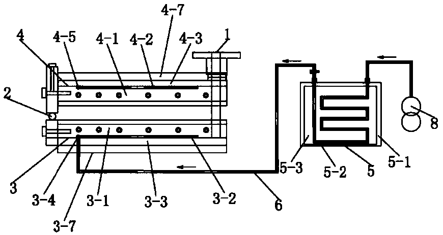
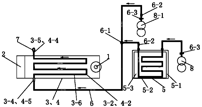
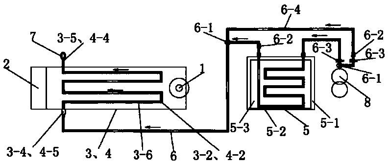
[0168] Such as Figure 1 to Figure 3 As shown, this embodiment provides a welding machine, including a lower electric heating splint 3 and an upper electric heating splint 4, the lower electric heating splint 3 is provided with a lower cold air circulation cooling channel 3-2, and the upper electric heating splint 4 is provided with The upper cold air circulation cooling passage 4-2, the lower cold air circulation cooling passage 3-2 and the upper cold air circulation cooling passage 4-2 communicate with the cold air source.

[0169] During the cooling process, the welding machine of this embodiment not only does not pollute the environment, but also greatly saves water resources, and can realize rapid cooling even if there is no water source.

[0170] Various improvements of this embodiment are described in detail below.

[0171] Such as Figure 1 to Figure 2 As shown, the cold air source is an air refrigeration device 5 .

[0172] The air refrigeration device 5 includes a...


PUM

PropertyMeasurementUnit
lengthaaaaaaaaaa

Abstract

The invention discloses a pressure maintaining and increasing hinge and a welding machine thereof. The pressure maintaining and increasing hinge comprises a first rotating connecting body, a second rotating connecting body and a hinging shaft; the first rotating connecting body and the second rotating connecting body are hinged with each other through the hinging shaft; the first rotating connecting body is separated into a rotating body and a connecting body; and the connecting body and the rotating body are connected with each other through a pressure maintaining elastic part. The welding machine comprises a lower electric heating clamping plate and an upper electric heating clamping plate; one end of the lower electric heating clamping plate is connected with one end of the upper electric heating clamping plate through a pressure increasing part; the other end of the lower electric heating clamping plate is connected with the other end of the upper electric heating clamping plate through a pressure increasing hinge; and the pressure increasing part is the pressure maintaining and increasing hinge. According to the pressure maintaining and increasing hinge and the welding machinethereof, after the pressure is applied to a water stop, although the water stop is heated and softened to be extruded to the surrounding, the pressures of the lower electric heating clamping plate and the upper electric heating clamping plate to the water stop are substantially constant so that the welding firmness of the water stop is greatly enhanced.

Description

technical field [0001] The invention relates to a pressurized hinge and a welding tool thereof, in particular to a pressure-holding pressurized hinge and a welding machine thereof. Background technique [0002] Since the length of the construction work surface is long or short, it is difficult to ensure that the length of the water stop is consistent with the length of the construction work surface. When the length of the construction work surface is less than the length of the waterstop, it is necessary to saw off the excess part of the waterstop. When the length of the construction work surface is greater than the length of the waterstop, the ends of the two waterstops need to be lapped together for welding. At this time, the waterstop welding machine is used. [0003] In the prior art, the waterstop welding machine includes a lower electric heating splint and an upper electric heating splint, one end of the lower electric heating splint and one end of the upper electric ...

Claims


Application Information

Patent Timeline
Patent Type & Authority Applications(China)
IPC IPC(8): B29C65/20
CPCB29C65/20B29C66/43
Inventor 高雄
Owner 佛山闽雄机电科技有限公司
Why Eureka
Try Eureka