A flying vehicle with folding wings for vertical take-off and landing

A flying car and vertical take-off and landing technology, which is applied in the field of flying cars, can solve the problems of high fuel consumption, high take-off and landing site requirements, and low lift efficiency, and achieve reasonable space occupation, high reliability, and high energy-to-weight ratio Effect

Pending Publication Date: 2018-12-18
西安艾尔维克航空科技有限公司
View PDF2 Cites 7 Cited by
  • Summary
  • Abstract
  • Description
  • Claims
  • Application Information

AI Technical Summary

Problems solved by technology

[0005] The invention solves the defects of long take-off and landing distance of flying cars in the prior art and high requirements for take-off and

Method used


Image

  • A flying vehicle with folding wings for vertical take-off and landing
  • A flying vehicle with folding wings for vertical take-off and landing
  • A flying vehicle with folding wings for vertical take-off and landing

Examples


Embodiment 1

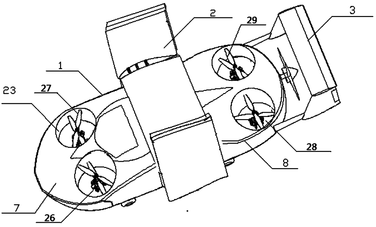
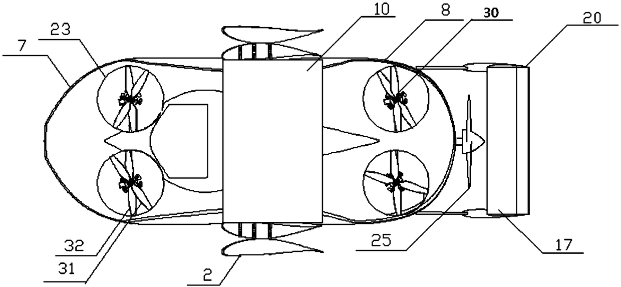
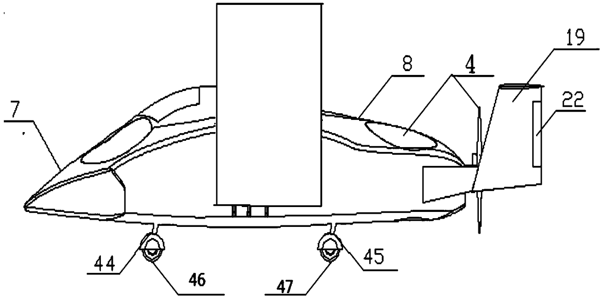
[0032] Example 1, such as Figure 1-Figure 10 As shown, the flying car with foldable vertical take-off and landing wings includes: a body 1 , a folding wing 2 , an empennage 3 , a power system 4 , a transmission mechanism 5 and a landing gear 6 . The body 1 adopts a normal car body in a streamlined form. The body 1 includes: a front body 7 and a rear body 8 . Wherein the cockpit 49 is placed in the inside of the front portion 7 of the vehicle body, 1.7m away from the center of gravity of the vehicle body 1 . The front part 7 of the vehicle body is an anti-collision structure with an airfoil shape and the same length as the widest part of the vehicle body. The front end of the front part 7 of the vehicle body has a large radian to meet the high-speed aerodynamic requirements during flight. On the one hand, this structure can protect the vehicle body, and on the other hand, it can provide a certain lift during flight. The shell of the body 1 adopts an aluminum alloy frame, and ...


PUM


Abstract

The invention belongs to the technical field of flying automobiles, in particular to a flying automobile with folding wings for vertical take-off and landing, which comprises a body, a folding wing, atail wing, a power system, a transmission mechanism and a landing gear. The power system is composed of a rotor duct system, a tail propeller and a pitch mechanism. The rotor duct system comprises four sets of coaxial dual rotor ducts. The invention solves the technical problems of long take-off and landing distance of flying vehicles, high requirements on take-off and landing sites, low liftingefficiency, high fuel consumption and insufficient stability of ducted rotor flying vehicles in the prior art. Higher lift acquisition rate, lower fuel consumption, higher reliability, higher safety,and lower cost.

Description

technical field [0001] The invention belongs to the technical field of flying cars, and in particular relates to a flying car with foldable vertical take-off and landing wings. Background technique [0002] A flying car is a means of transportation that can fly in the air and drive on the ground. It is a combination of an airplane and a car. With the rapid increase of the world's population and the improvement of the economic level, the human demand for automobiles is also growing rapidly. The resulting ground traffic jam problem will be more serious. Considering the complexity of road traffic conditions in the future, if the common taxiing method is adopted, many outstanding problems will have to be faced. For example, the taxiing take-off and landing method of an aircraft has high requirements on the quality of the road, such as the planar shape of the road, because a relatively straight road section with a long extension distance needs to be provided during the take-off...

Claims


Application Information

Patent Timeline
IPC IPC(8): B60F5/02B64C1/30B64C29/00
CPCB64C1/30B64C29/00B60F5/02
Inventor 李占科薛鲲岳韩超李少峰刘秧郭佼杨影
Owner 西安艾尔维克航空科技有限公司
Why Eureka
Try Eureka