Two-way lock box structure and door/window using structure
A two-way lock and transmission technology, applied in the field of doors/windows, can solve the problems of unstable internal structure, lack of anti-theft structure, uneven force on connecting rods, etc., and achieve the effects of simple structure, balanced structure and high resistance to deformation.
- Summary
- Abstract
- Description
- Claims
- Application Information
AI Technical Summary
Problems solved by technology
Method used
Image

Examples
Embodiment Construction
[0022] The present invention will be further described below in conjunction with accompanying drawing:
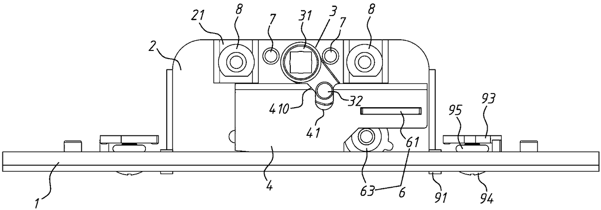
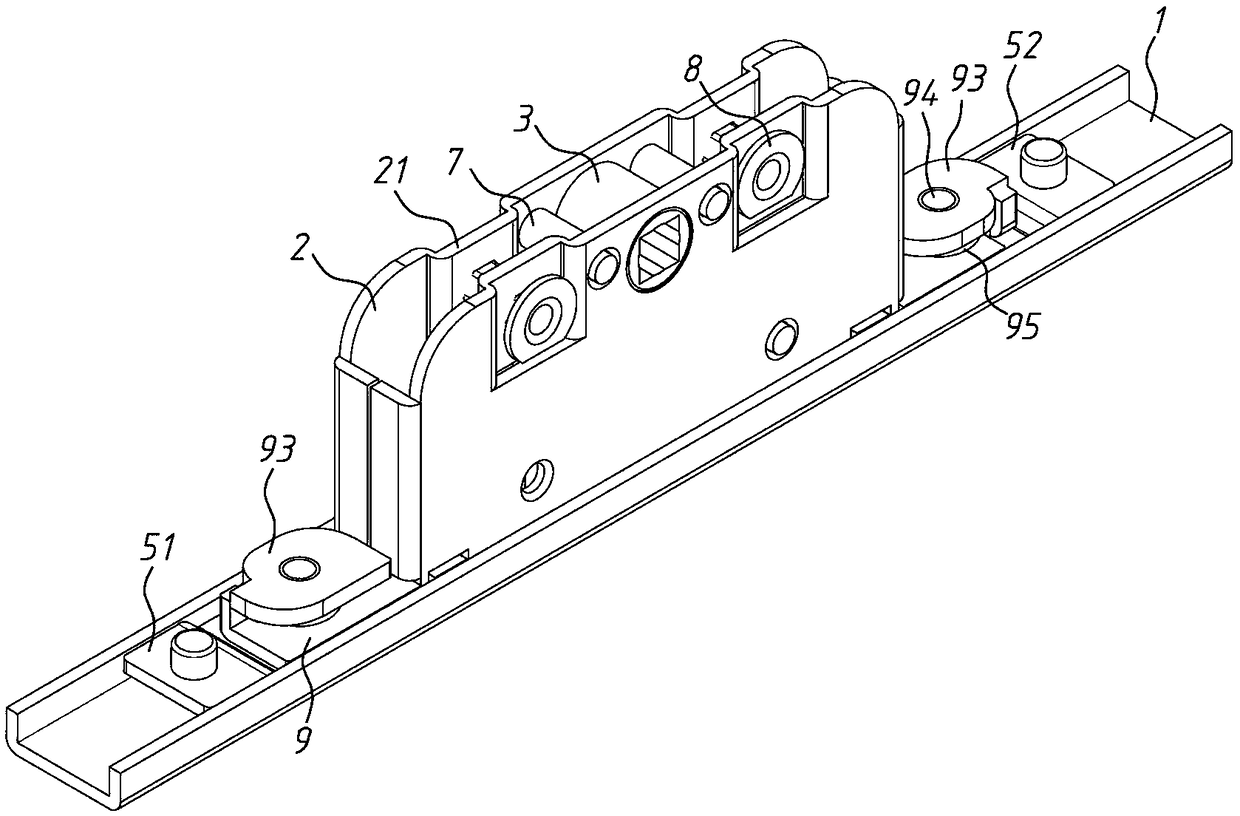
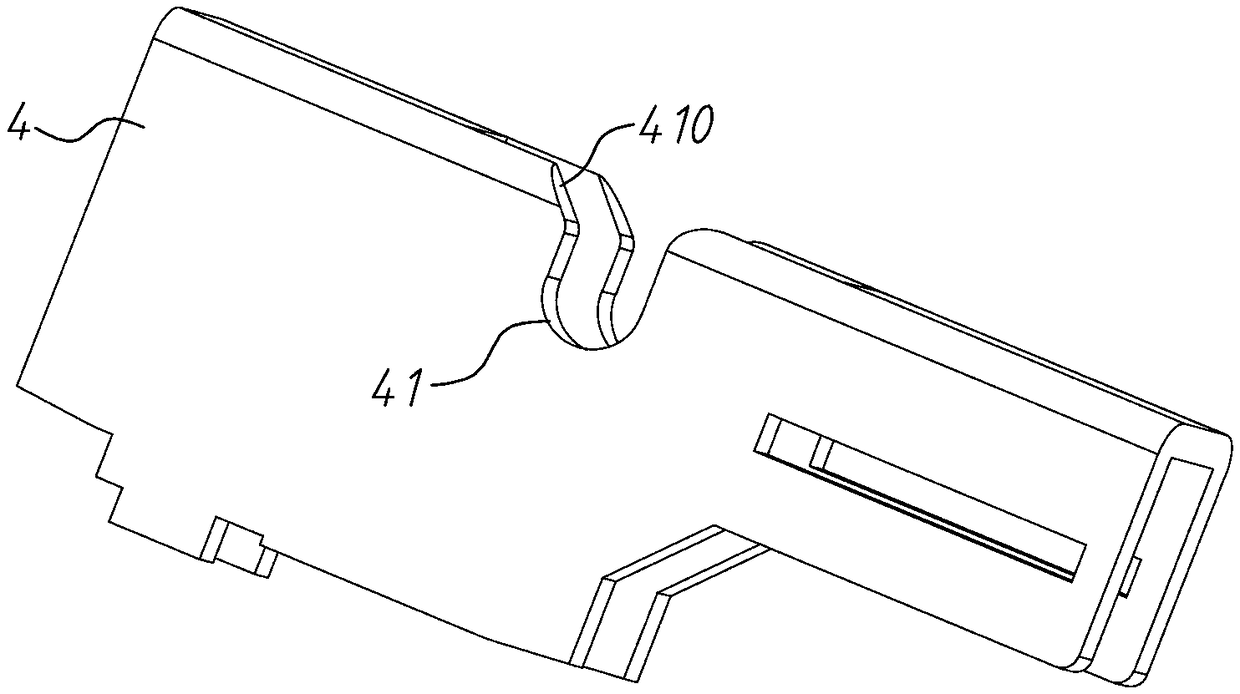
[0023] refer to Figure 1 to Figure 5 The two-way lock box structure shown includes a strip-shaped bottom plate 1, two panels 2 parallel to each other vertically installed on the bottom plate 1, and a rotating handle 3 hinged between the panels 2, sandwiched between the panels 2 The transmission member 4, the first transmission bar 51 that is linked with the transmission member 4 and slides along the bottom plate 1, and the first transmission bar 51 that is reversely driven by the transmission member 4 through the rack and pinion assembly 6 and slides along the bottom plate 1 Two transmission bars 52. The bottom plate 1 is preferably in the shape of a chute, and of course it can also be in the shape of a guide rail, which is mainly used for installing panels and for driving and positioning each driving strip. The turning handle 3 includes a hinge shaft 31 and a radially c...
PUM
 Abstract
Description
Claims
Application Information
 - R&D
- Intellectual Property
- Life Sciences
- Materials
- Tech Scout
- Unparalleled Data Quality
- Higher Quality Content
- 60% Fewer Hallucinations
Browse by: Latest US Patents, China's latest patents, Technical Efficacy Thesaurus, Application Domain, Technology Topic, Popular Technical Reports.
© 2025 PatSnap. All rights reserved.Legal|Privacy policy|Modern Slavery Act Transparency Statement|Sitemap|About US| Contact US: help@patsnap.com