Magnetic lock device and parking device

a magnetic lock and magnetic technology, applied in mechanical devices, braking systems, transportation and packaging, etc., can solve the problems of quenching, inability to harden at least the surface etc., to improve the magnetic efficiency of the holding solenoid, and improve the strength of the part of the movable elemen

Active Publication Date: 2019-08-20
AISIN AW CO LTD
View PDF13 Cites 0 Cited by
  • Summary
  • Abstract
  • Description
  • Claims
  • Application Information

AI Technical Summary

Benefits of technology

[0006]In the parking device described above, when the parking release state is kept by the engagement between the roller supported by the movable element and the concave portion formed in the parking rod, a load in a direction orthogonal to the movement direction of the movable element (the movement direction of the parking rod) is applied to the movable element. Therefore, it is important to improve the strength (hardness) of the part of the movable element to which a force is applied from the parking rod via the roller. On the other hand, the movable element is preferably made of non-magnetic material to improve the magnetic efficiency of the holding solenoid. In this case, however, it is impossible to perform surface effect treatment for hardening at least the surface of the movable element, such as quenching. Accordingly, it is necessary to improve the strength of the part of the movable element to which a force is applied from the parking rod via the roller and improve the magnetic efficiency of the holding solenoid at the same time.
[0007]A main object of the magnetic lock device and parking device according to the disclosure is to improve the durability of a movement restricting member of a magnetic lock device that restricts the movement of a moving member reciprocating in a first direction using a magnetic force and improve the magnetic efficiency of the magnetic lock device at the same time.
[0018]Since the first member is surface-hardened, it is possible to suppress deformation (such as concave portion of the surface) of the first member due to a force given from the bearing and a force applied from the abutted portion to the abutting portion when the abutted portion abuts against the abutting portion, thereby improving the durability of the first member. When the abutted portion abuts against the abutting portion, a force in a direction different from the movement direction of the first member and the second member is applied from the abutted portion to the abutting portion. Accordingly, a larger force may be applied from the bearing to the first member than in the case in which the abutted portion does not abut against the abutting portion. Accordingly, it is important to improve the hardness of the first member against the abutment between the abutted portion and the abutting portion. “Surface-hardening” is, for example, quenching. In addition, since the second member is made of non-magnetic material, it is possible to prevent magnetic flux leakage due to the second member and improve the magnetic efficiency of the magnetic lock device. As a result, it is possible to improve the durability of the first member of the magnetic lock device and improve the magnetic efficiency of the magnetic lock device at the same time.
[0020]The parking device according to the disclosure includes the magnetic lock device according to any one of the above aspects of the disclosure. Accordingly, it is possible to obtain the same effect as in the magnetic lock device according to the disclosure, such as, for example, the effect of improving the durability of the first member of the magnetic lock device and improving the magnetic efficiency of the magnetic lock device at the same time. The moving member and the movement restricting member are disposed so that the moving member and the movement restricting member are moved in directions orthogonal to each other. This facilitates disposition in a restricted space as compared with the case in which both members are disposed (in a single shaft line) so as to move in a single direction.

Problems solved by technology

In this case, however, it is impossible to perform surface effect treatment for hardening at least the surface of the movable element, such as quenching.

Method used


Image

  • Magnetic lock device and parking device
  • Magnetic lock device and parking device
  • Magnetic lock device and parking device

Examples


Embodiment Construction

[0033]Next, an embodiment of the disclosure will be described with reference to the drawings.

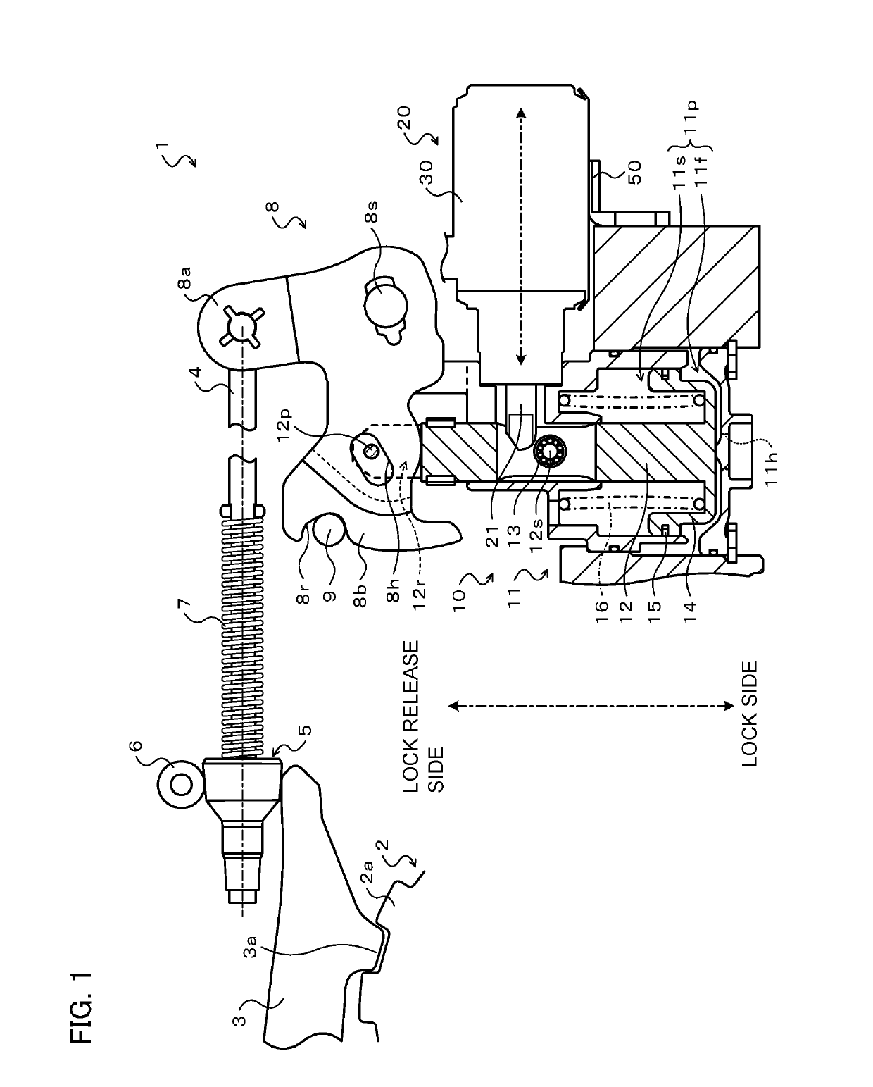
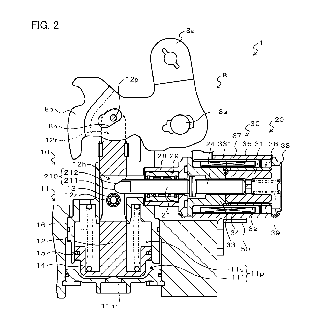
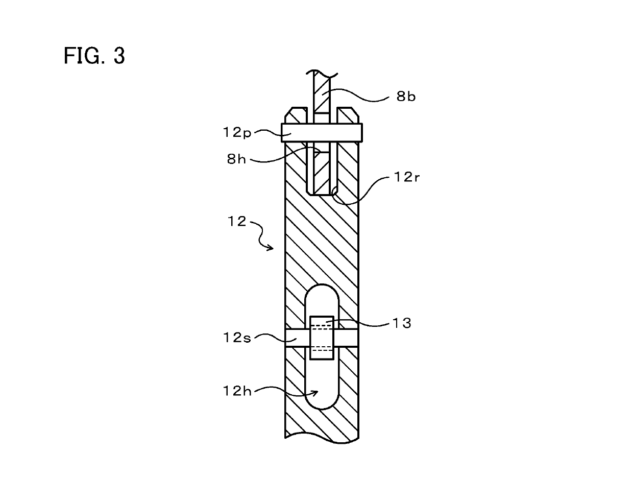
[0034]FIG. 1 is a structural diagram schematically illustrating the structure of the parking device 1 according to the embodiment of the disclosure, FIG. 2 is a structural diagram schematically illustrating the structure of the main part of the parking device 1, FIG. 3 is a structural diagram schematically illustrating the structure of a part of the hydraulic pressure actuator 10, and FIG. 4 is a structural diagram schematically illustrating the structure of the magnetic lock device 20.

[0035]The parking device 1 according to the embodiment is mounted in a vehicle and disposed inside or outside the transmission case of a transmission (not illustrated). This parking device 1 is configured as a so-called shift-by-wire parking device that locks any one of rotary shafts of the transmission based on an electric signal output according to the operation position (shift range) of a shift lever and re...


PUM


Abstract

A magnetic lock device includes a lock shaft having an abutting portion capable of abutting against a roller of a piston rod of a hydraulic pressure actuator, a transfer shaft configured separately from the lock shaft, the transfer shaft abutting against an end surface of the lock shaft, and a magnetic portion locking (restricting movement to the right side in the drawing) the lock shaft, the transfer shaft, and a plunger by attracting the plunger toward an attracting portion using a magnetic force. The lock shaft is surface-hardened to have a higher hardness and the transfer shaft is made of non-magnetic material.

Description

CROSS REFERENCE TO RELATED APPLICATIONS[0001]This application is a National Stage of International Application No. PCT / JP2015 / 072821 filed Aug. 12, 2015, claiming priority based on Japanese Patent Application Nos. 2014-176391 filed Aug. 29, 2014 and 2014-176392 filed Aug. 29, 2014, the contents of all of which are incorporated herein by reference in their entirety.TECHNICAL FIELD[0002]The present disclosure relates to a magnetic lock device and a parking device.BACKGROUND ART[0003]Conventionally, there is a known parking device including a parking rod performing engagement and disengagement between a parking pawl and a parking gear by moving in the axial direction, a parking lock spring biasing the parking rod to the side in the axial direction (of the parking rod) that engages (forms a parking lock state) the parking pawl with the parking gear, a hydraulic cylinder moving the parking rod to the side in the axial direction (of the parking rod) that releases (forms a parking release ...

Claims


Application Information

Patent Timeline
Patent Type & Authority Patents(United States)
IPC IPC(8): F16H63/34B60T1/00B60T1/06F16D63/00
CPCF16H63/3433B60T1/005F16H63/3483F16D63/006F16H63/3475B60T1/062
Inventor KOKUBU, TAKAHIRONAKAI, MASAYA
Owner AISIN AW CO LTD
Why Eureka
Try Eureka