LED light source lens device

A LED light source and lens technology, applied in the field of LED light source lens devices, can solve the problems of inconvenient holding and carrying, inconvenient lens cleaning, and low use range, so as to improve the convenience of installation, improve the comfort of holding, and expand the holding range effect

Inactive Publication Date: 2018-12-18
珠海市德新合利电子科技有限公司
View PDF0 Cites 1 Cited by
  • Summary
  • Abstract
  • Description
  • Claims
  • Application Information

AI Technical Summary

Problems solved by technology

[0002] The existing LED light source lens device is not convenient to clean the lens, nor is it convenient to protect the lens, thus increasing the probability of lens collision damage. The existing LED light source lens device is usually fixed on the bracket with bolts for use. Not easy to hold and carry, low range of use

Method used


Image

  • LED light source lens device
  • LED light source lens device
  • LED light source lens device

Examples


Embodiment Construction

[0020] In order to make the technical means, creative features, goals and effects achieved by the present invention easy to understand, the present invention will be further described below in conjunction with specific embodiments.

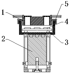
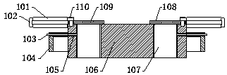
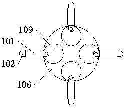
[0021] see Figure 1-Figure 4 , the present invention provides a technical solution: a LED light source lens device, including a cleaning mechanism 1, a holding mechanism 2, a circuit board 3, a patch light source 4 and a protective shell 5, and the holding mechanism 2 is connected to the lower end surface of the protective shell 5 , the circuit board 3 is fixed on the lower part of the protective shell 5 through the supporting legs, the patch light source 4 is welded on the upper end surface of the circuit board 3, the cleaning mechanism 1 is set on the upper end of the protective shell 5, and the cleaning mechanism 1 includes a cleaning cotton cover 101, a U-shaped frame 102, Connecting rod 103, connecting sleeve plate 104, threaded rod 105, baf...


PUM


Abstract

The invention provides an LED light source lens device which comprises a cleaning mechanism, a holding mechanism, a circuit board, an SMD light source and a protection shell. The holding mechanism isconnected to the lower end face of the protection shell. The circuit board is fixed to the inner lower portion of the protection shell through supporting legs. The SMD light source is welded to the upper end face of the circuit board. The cleaning mechanism is mounted at the upper end of the protection shell in a sleeving manner and comprises cleaning cotton sleeves, a U-shaped frame, a connectingrod, a connecting sleeve plate, a threaded rod, a baffle, lens bodiesy, containing grooves, a cover plate and a fixed rod. The holding mechanism comprises handle rods, an open groove, a sliding groove, a fastening bolt, a sliding block, through holes, an adjusting bolt, a bottom plate, a first threaded hole, a handle and micro suction cups. Compared with the prior art, the LED light source lens device has the following advantages that the protection function and the cleaning function are achieved, mounting convenience is also improved, the holding function is achieved, and turning adjustmentis facilitated.

Description

technical field [0001] The invention is an LED light source lens device, which belongs to the field of LED light source equipment. Background technique [0002] The existing LED light source lens device is not convenient to clean the lens, nor is it convenient to protect the lens, thus increasing the probability of lens collision damage. The existing LED light source lens device is usually fixed on the bracket with bolts for use. It is inconvenient to hold and carry, and the use range is low. Contents of the invention [0003] In view of the deficiencies in the prior art, the purpose of the present invention is to provide an LED light source lens device to solve the problems raised in the background art above. [0004] In order to achieve the above object, the present invention is achieved through the following technical solutions: a LED light source lens device, including a cleaning mechanism, a holding mechanism, a circuit board, a patch light source and a protective sh...

Claims


Application Information

Patent Timeline
Patent Type & Authority Applications(China)
IPC IPC(8): F21L2/00F21V33/00F21V17/10F21V21/40F21V14/00B08B1/04F21Y115/10
CPCF21L2/00B08B1/006B08B1/04F21V14/00F21V17/10F21V21/40F21V33/00F21Y2115/10
Inventor 刘志勇黎光羽李嵩崴
Owner 珠海市德新合利电子科技有限公司
Why Eureka
Try Eureka