
Solar automatic distiller used for collecting lights on the basis of light reflection principle

A solar energy and distiller technology, applied in the field of solar automatic distiller, can solve heating and other problems

Active Publication Date: 2018-12-18
浙江欧托电气有限公司
View PDF11 Cites 0 Cited by
  • Summary
  • Abstract
  • Description
  • Claims
  • Application Information

AI Technical Summary

Problems solved by technology

[0003] The solar automatic distiller must rely on the high water temperature after being heated. The specific gravity of the water is light. Using the principle of water pressure and hot water, it needs to return the water from the top of the solar silicon tube to the water storage tank. Therefore, the solar silicon tube must have a certain inclination angle. As far as the northern hemisphere is concerned, solar silicon tubes should be inclined to the south, generally installed at an inclination of 45 degrees. In addition to the polar day and polar night areas in the northern hemisphere in summer, the sun rises in the northeast and sets in the northwest. When the solar silicon tube is facing the sun, it can get sunlight. The light obtained in the sun is extremely weak, and when the sun is behind, it cannot heat the water in the solar silicon tube, so there is a time limit for desalination of seawater through the solar automatic still

Method used


Image

  • Solar automatic distiller used for collecting lights on the basis of light reflection principle
  • Solar automatic distiller used for collecting lights on the basis of light reflection principle
  • Solar automatic distiller used for collecting lights on the basis of light reflection principle

Examples


Embodiment Construction

[0023] The technical solutions in the embodiments of the present invention will be clearly and completely described below in conjunction with the accompanying drawings in the embodiments of the present invention. Obviously, the described embodiments are only a part of the embodiments of the present invention, rather than all the embodiments. Based on the embodiments of the present invention, all other embodiments obtained by those of ordinary skill in the art without creative work shall fall within the protection scope of the present invention.

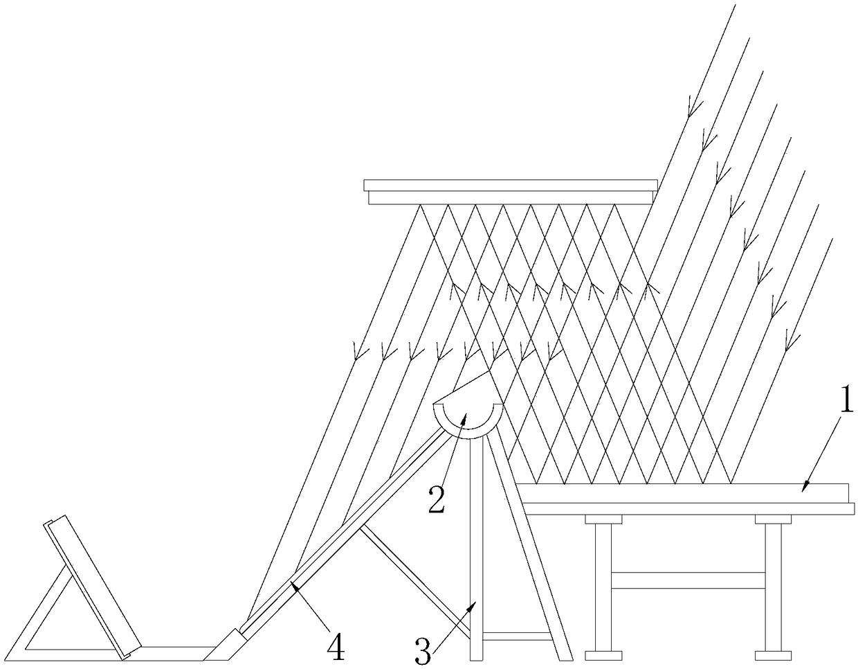
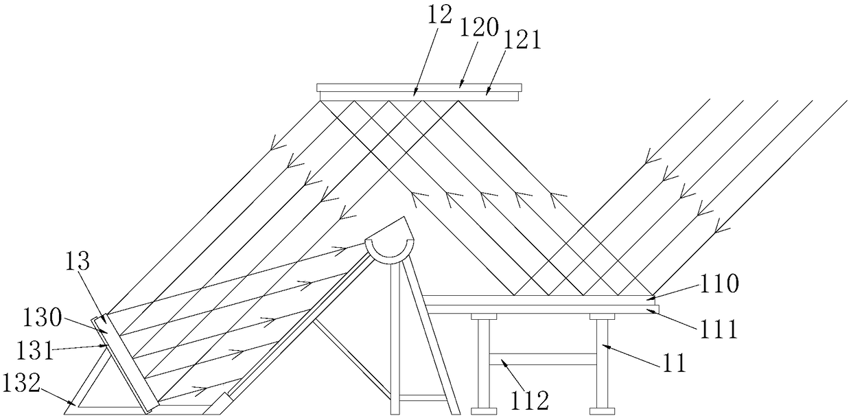
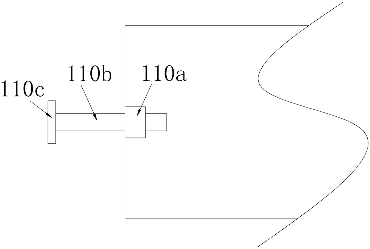
[0024] See Figure 1-4 , The present invention provides a technical solution for a solar automatic distiller based on the principle of light reflection for collecting light: its structure includes a light collecting device 1, a water storage tank 2, a distiller body 4, and a solar silicon tube 4, the distiller The solar silicon tubes 4 are uniformly installed on an inclined surface of the body 4, and the solar silicon tubes 4 are arrange...


PUM


Abstract

The invention discloses a solar automatic distiller used for collecting lights on the basis of a light reflection principle. The structure of the solar automatic distiller used for collecting lights on the basis of the light reflection principle comprises a light collection device, a water storage tank, a distiller body and solar silicon tubes; solar silicon tubes are uniformly mounted on one inclined surface of the distiller body; and eight and more than eight solar silicon tubes are arranged in an equally spaced manner and arranged with inclination angles of 45 degrees. Compared with the prior art, the solar automatic distiller used for collecting lights on the basis of the light reflection principle has the beneficial effects that incident lights with angles of larger than 0 degree or less than or equal to 45 degrees can be indirectly reflected to the solar silicon tubes and the water storage tank through a first polishing plate on the basis of the light reflection principle and thelight reflection law when the solar silicon tubes are in a shady state because three polishing plates are arranged on the solar automatic distiller; and therefore, the solar silicon tubes and the water storage tank can also be illuminated by sunlight when being in the shady state so that the solar silicon tubes and the water storage tank can absorb heat to heat seawater; the seawater is vaporizedinto water vapor; and the water vapor is condensed into distilled water so as to achieve a purpose of desalting the seawater.

Description

Technical field [0001] The invention relates to the technical field of seawater desalination treatment, in particular to a solar automatic distiller for collecting light based on the principle of light reflection. Background technique [0002] The solar automatic distiller is designed according to the principle of "hot box" and is converted from a solar water heater. It uses solar energy to heat the seawater temperature to vaporize it into water vapor, and the water vapor condenses into distilled water to desalinate the seawater. [0003] The solar automatic distiller must rely on heating, the water with high water temperature has a lighter specific gravity. Using the principle of light water pressure and hot water, the water needs to be returned from the top of the solar silicon tube to the water storage tank, so the solar silicon tube must have a certain inclination angle. As far as the northern hemisphere is concerned, the solar silicon tube should be tilted to the south, genera...

Claims


Application Information

Patent Timeline
Patent Type & Authority Applications(China)
IPC IPC(8): F24S20/30F24S23/79
CPCY02E10/40Y02A20/142
Inventor 不公告发明人
Owner 浙江欧托电气有限公司
Learn More