Aeroengine blade vibration test device and method

An aero-engine and vibration testing technology, which is applied in vibration testing, machine/structural component testing, measuring devices, etc., can solve the problems of single clamping blade direction, low test efficiency, single clamping blade specification, etc., to achieve any performance, expand the test range, and ensure the effect of preload

Active Publication Date: 2018-12-18
YANTAI UNIV
View PDF9 Cites 7 Cited by
  • Summary
  • Abstract
  • Description
  • Claims
  • Application Information

AI Technical Summary

Problems solved by technology

[0004] 1. The compressor and gas turbine in the aero-engine cover multi-stage blades. Among them, the compressor blades mainly use dovetail-shaped tenons, and the turbine blades mainly use fir tree-shaped tenons. The structural parameters of different blade tenons are different. Therefore, the blade vibration test test The test device is required to be able to clamp blades of various specifications, but the traditional test device clamps blades with a single specification, which cannot meet the actual test requirements;
[0005] 2. The blade vibration test requires that the test device can measure the mode and response of the blade at any angle, but the traditional test device clamps the blade in a single direction, which cannot meet the test requirements;
[0006] 3. The existing test device cannot realize the vibration test of the blade at any angle, and the design of the briquetting block cannot rotate with the change of the test angle, which cannot guarantee the pre-tightening force of the blade during the test
[0007] The above deficiencies lead to time-consuming, labor-intensive and high-cost test of blade vibration test, and low test efficiency. Therefore, there is an urgent need for an aero-engine blade vibration test device that can solve the above technical problems.

Method used


Image

  • Aeroengine blade vibration test device and method
  • Aeroengine blade vibration test device and method
  • Aeroengine blade vibration test device and method

Examples


Embodiment 2

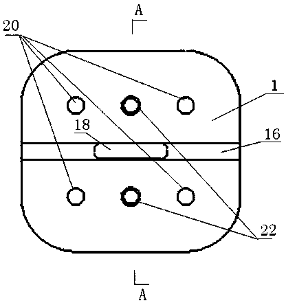
[0052] The difference between this embodiment and Embodiment 1 is that the tenon groove 16 runs through the entire length direction of the rotating disk 1, and the shape of the tenon groove 16 depends on the shape of the blade tenon 19. The blade tenon 19 is in the shape of a fir tree, and the tenon 16 is in the shape of a fir tree type.

Embodiment 3

[0054] The test method of a kind of aeroengine blade vibration test test device of the present embodiment comprises the following steps:

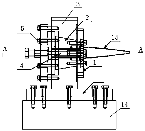
[0055] 1. Install the device main body 3 on the vibrating table 14;

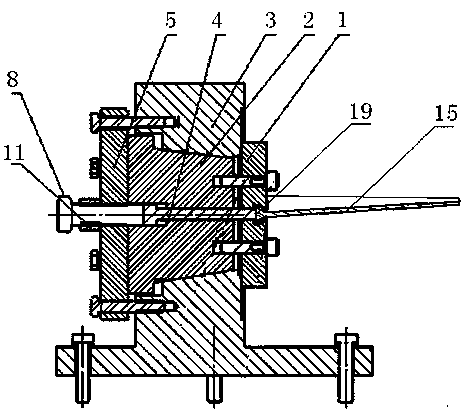
[0056] 2. Put the back cover 2 into the back cover installation chamber 12 of the main body 3 of the device. Since both are provided with tapers, in order to facilitate the subsequent steps, do not use force when putting the back cover 2 into the main body 3 of the device in this step. push tight;

[0057] 3. Determine the shape and size of the tenon and groove of the rotating disk 1 according to the shape and size of the blade tenon 19;

[0058] 4. Install the rotating disk 1 on the rear cover 2 and position it;

[0059] 5. Put the pressing block 4 into the back cover 2, insert the blade tenon 19 into the tenon groove 16 of the rotating disk 1, push the pressing block 4 by hand, make it contact with the blade tenon 19 and make the blade tenon 19 and the rotating disk ...


PUM


Abstract

The invention relates to an aeroengine blade vibration test device, and belonging to the technical field of engine blade test devices. The aeroengine blade vibration test device comprises a device main body arranged on a shaking table, wherein a rotating disc for inserting blades is arranged outside the device main body; a rear cover for driving the rotating disc to rotate is arranged inside the device main body; a rotating disc is arranged on one side of the rear cover, and a clamping disc is arranged on the other side of the rear cover; a rear cover chamber passing through a pressing block is arranged along the height direction of the rear cover; and the rotating disc is provided with a rotating disc chamber communicating with the rear cover chamber and a mortise groove for inserting blades. The aeroengine blade vibration test device is suitable for testing blades of various structures, can realize vibration tests of the blades at any angle, and has high test accuracy and accuracy.

Description

technical field [0001] The invention relates to a vibration test device for aeroengine blades, belonging to the technical field of engine blade test devices. Background technique [0002] Blades are one of the important parts of aero-engines, mainly used in compressors and gas turbines. Among them, the compressor blades are not only subject to high centrifugal load, aerodynamic load, atmospheric temperature difference load and vibration alternating load, but also are impacted by foreign objects in the engine intake passage, and are eroded by wind, sand and humidity. Turbine blades not only bear the corrosion and erosion caused by high temperature, but also bear the huge centrifugal force, aerodynamic force and vibration load caused by high-speed rotation. It can be seen that the working condition of the blade is very bad, and it is one of the main parts that determine the life of the engine. Therefore, the blade must go through vibration assessment, function assessment and...

Claims


Application Information

Patent Timeline
Patent Type & Authority Applications(China)
IPC IPC(8): G01M7/02
CPCG01M7/02
Inventor 王娇于涛张凱尧张曰浩童桂英高培鑫
Owner YANTAI UNIV
Why Eureka
Try Eureka