
Fault detection device of electrified railway switching station, and method thereof

An electrified railway, fault detection technology

Active Publication Date: 2018-12-18
SOUTHWEST JIAOTONG UNIV
View PDF14 Cites 7 Cited by
  • Summary
  • Abstract
  • Description
  • Claims
  • Application Information

AI Technical Summary

Problems solved by technology

[0004] The purpose of the present invention is to provide a fault detection device and method for an electrified railway switching station, which can effectively solve the technical problems in the prior art that faults cannot be found and isolated in a timely and accurate manner, and can completely eliminate the faults of the train through control. When driving from a non-fault section to a fault section, the pantograph short-connects the catenary to cause a new short circuit and the train enters the non-electric zone with load, causing arcing and burning, or even blowing the catenary to cause accidents and hidden dangers, thereby improving The reliability of the power supply system and the efficiency of railway transportation

Method used


Image

  • Fault detection device of electrified railway switching station, and method thereof
  • Fault detection device of electrified railway switching station, and method thereof
  • Fault detection device of electrified railway switching station, and method thereof

Examples


Embodiment 1

[0031] like figure 1 and figure 2 As shown, the embodiment of the present invention provides a fault detection device for an electrified railway switch station, which is installed in the middle switch station KB2. KB2, the test terminal of the right adjacent switching station KB3, its output terminal is connected to the control terminal of the left adjacent switching station KB1, the middle switching station KB2, the right adjacent switching station KB3 and the ESC information sending terminal DD, wherein the The left adjacent switching station KB1, the middle switching station KB2, and the right adjacent switching station KB3 are respectively provided with two sectionalizers on the catenary T at their respective exits, and the sectionalizers are connected by a transition zone Ta.

[0032] In the embodiment of the present invention, the test terminal of the left adjacent switching station KB1 is the test terminal of the second current transformer LH12, and the control termin...

Embodiment 2

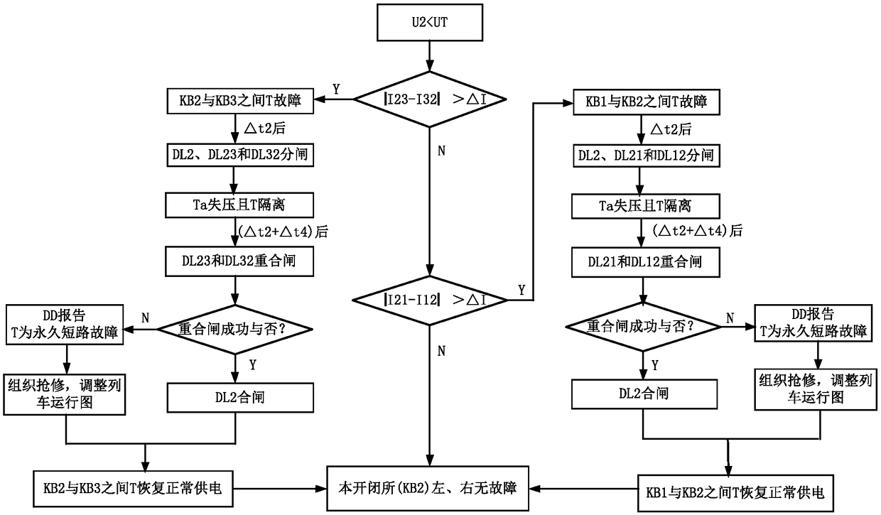
[0039] like image 3 As shown, the embodiment of the present invention provides a fault detection method for electrified railway switching stations using the fault detection device described in the first embodiment above. The fault detection device is installed in the middle switching station KB2, and the train converter is set The closing reaction time of the network side is △t1, the opening time of the catenary T circuit breaker is △t2, the time interval for the train converter to resume normal operation after detecting that the catenary voltage is normal is △t3, and the catenary T is reclosed after short circuit The specific steps of the detection method are as follows: determine whether the voltage value U2 measured by the second voltage transformer YH2 is lower than the state threshold UT;

[0040] If yes, the train loses pressure and is in the range of pressure loss. After △t1 second, the grid side of the train converter is closed. At this time, the load = 0, and at the ...


PUM


Abstract

The invention discloses a fault detection device of an electrified railway switching station, and a method thereof, and relates to the technical field of the electrified railway traction power supply.The fault detection device is arranged at a middle switching station, an output end thereof is connected with control ends and electric control information sending ends of a left neighbor switching station, the middle switching station, and a right neighbor switching station; two sectionalizers are arranged on a contact network of an exit of each of the left neighbor switching station, the middleswitching station and the right switching station, and the sectionalizers are connected through a transition area. The fault can be accurately discovered and isolated in time, the technical problemsthat the new short-circuit is caused by short-circuit of pantograph and the contact network when the train drives into a fault section from the non-fault section and the arcing and burning loss are caused since the train with the load enters a nonelectric area, even if the accident is caused since the contact network is burnout in the prior art can be effectively solved.

Description

technical field [0001] The invention belongs to the technical field of AC electrified railway traction power supply and measurement and control. Background technique [0002] Direct power supply (direct supply) occupies the majority of electrified railways, and it has many advantages such as simple structure, less investment, and easy maintenance and repair. Obviously, in the direct supply mode, long-distance power supply in traction substations or through-type in-phase power supply between adjacent traction substations can reduce or eliminate dead zones, thereby improving power supply capacity. At the same time, in order to limit the fault to a minimum range and ensure a wider range of normal power supply, the traction network is required to realize segmental power supply, that is, to install a sectionalizer on the catenary and set up a switching station to realize segmental removal of the fault ,isolation. But, this subsection method also can bring new problem when caten...

Claims


Application Information

Patent Timeline
Patent Type & Authority Applications(China)
IPC IPC(8): G01R31/08G01R31/02
CPCG01R31/086G01R31/50Y04S10/52
Inventor 李群湛易东陈民武
Owner SOUTHWEST JIAOTONG UNIV
Learn More