Simulation test method and system of valve control device based on FPGA

A technology of simulation testing and valve control, applied in general control systems, control/regulation systems, instruments, etc., can solve the problems of in-depth and comprehensive testing without valve control functions, and the inability to conduct in-depth and comprehensive tests of valve control functions, etc.

Inactive Publication Date: 2018-12-18
ELECTRIC POWER RESEARCH INSTITUTE, CHINA SOUTHERN POWER GRID CO LTD +1
View PDF5 Cites 8 Cited by
  • Summary
  • Abstract
  • Description
  • Claims
  • Application Information

AI Technical Summary

Problems solved by technology

[0003] In the localization process of conventional DC projects, although the valve control device participated in the real-time closed-loop test of the DC protection system, a valve in the simulation model was simulated with a switch signal, and the trigger pulse was a long pulse of 6 ms, which was controlled by the simulation. Due to platform limitations, the valve control function cannot be tested in depth and comprehensively; domestic related equipment manufacturers have used a simplified primary converter valve device connected to the valve control device to establish a dynamic model system for testing, but based on the real-time simulation system for the converter valve The idea of ​​carrying out detailed and accurate modeling and connecting the valve control device with the control and protection device to conduct a complete test of the valve control function has not been realized in-depth and comprehensive for the valve control function due to the limitations of the simulation platform and simulation method. test

Method used


Image

  • Simulation test method and system of valve control device based on FPGA
  • Simulation test method and system of valve control device based on FPGA

Examples


Embodiment Construction

[0041]The following will clearly and completely describe the technical solutions in the embodiments of the present invention with reference to the accompanying drawings in the embodiments of the present invention. Obviously, the described embodiments are only some, not all, embodiments of the present invention. Based on the embodiments of the present invention, all other embodiments obtained by persons of ordinary skill in the art without creative efforts fall within the protection scope of the present invention.

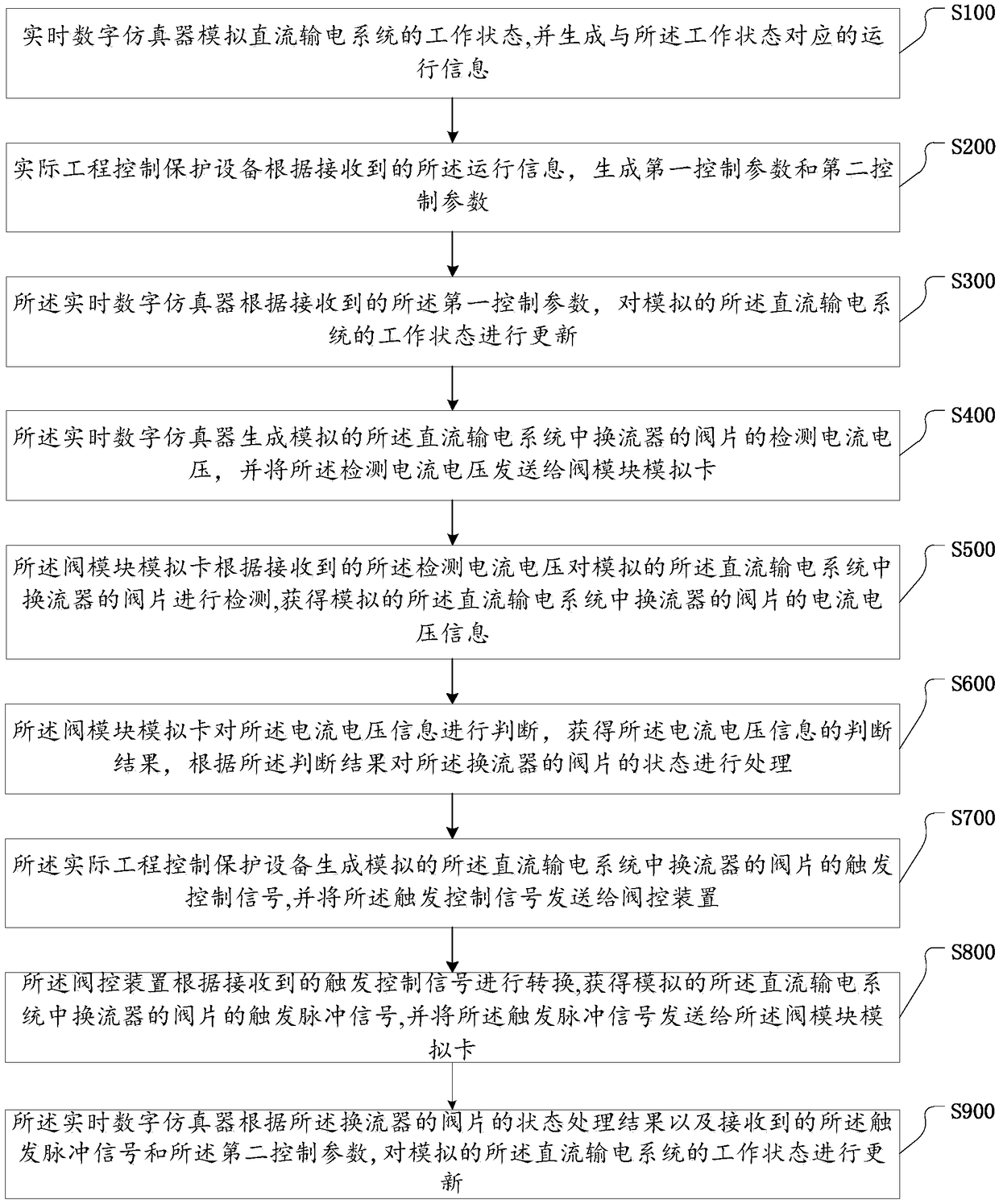
[0042] see figure 1 , which is a schematic flow chart of a simulation test method for an FPGA-based valve control device provided in an embodiment of the present invention, the simulation test method for an FPGA-based valve control device includes:

[0043] S100: The real-time digital simulator simulates the working state of the direct current transmission system, and generates operation information corresponding to the working state;

[0044] S200: The actual engi...


PUM


Abstract

The invention discloses a simulation test method and system of a valve control device based on an FPGA. The method comprises the following steps: a real-time digital simulator simulates a working state of a direct current transmission system, and generates operation information corresponding to the working state; an actual engineering control protection device generates a first control parameter and a second control parameter according to the received operation information; and the real-time digital simulator respectively updates the simulated working state of the direct current transmission system according to the received first control parameter, a trigger pulse signal, the second control parameter and a state processing result of a valve block of a transverter. According to the method,the devices excluding the valve control device in a valve control system are simulated by using a valve module simulation card on the basis of the existing direct current control protection platform technology, wherein the valve module simulation card mainly performs valve block level simulation on the valve block of the transverter to perform an in-depth and comprehensive complete test on the valve control device so as to improve the simulation test capability and level of the valve control device.

Description

technical field [0001] The invention relates to the technical field of high-voltage direct current transmission, in particular to an FPGA-based simulation test method and system for a valve control device. Background technique [0002] The valve control device of the DC transmission system is the main component of the converter valve equipment, the part that connects the control system of the converter station with the primary equipment of the converter valve, and is one of the key equipment to ensure the reliable operation of the DC transmission system. The complete test of the function of the valve control device in the DC transmission system plays an important role in discovering the functional defects of the valve control device and improving the function of the valve control device. For a long time, the valve control device has been regarded as an accessory device of the primary converter valve equipment, and its control-related functions have not received sufficient at...

Claims


Application Information

Patent Timeline
Patent Type & Authority Applications(China)
IPC IPC(8): G05B17/02
CPCG05B17/02
Inventor 李书勇郭琦刘志江陈德杨
Owner ELECTRIC POWER RESEARCH INSTITUTE, CHINA SOUTHERN POWER GRID CO LTD
Why Eureka
Try Eureka