
Money twisting mechanism of money counter

A technology of a banknote counting machine and a banknote twisting wheel, which is applied to the counting mechanism/item, the counting of items shipped through a conveying device, instruments, etc. Convenience and the effect of maintaining friction

Inactive Publication Date: 2018-12-18
PINGYANG RANPENG ELECTRONICS MACHINERY
View PDF7 Cites 2 Cited by
  • Summary
  • Abstract
  • Description
  • Claims
  • Application Information

AI Technical Summary

Problems solved by technology

[0004] The purpose of the present invention is to solve the problem that the twisting rubber ring on the twisting wheel in the prior art is difficult to replace after being worn out, and proposes a twisting mechanism for a banknote counter

Method used


Image

  • Money twisting mechanism of money counter
  • Money twisting mechanism of money counter
  • Money twisting mechanism of money counter

Examples


Embodiment Construction

[0026] The following will clearly and completely describe the technical solutions in the embodiments of the present invention with reference to the accompanying drawings in the embodiments of the present invention. Obviously, the described embodiments are only some, not all, embodiments of the present invention.

[0027] In describing the present invention, it should be understood that the terms "upper", "lower", "front", "rear", "left", "right", "top", "bottom", "inner", " The orientation or positional relationship indicated by "outside", etc. is based on the orientation or positional relationship shown in the drawings, and is only for the convenience of describing the present invention and simplifying the description, rather than indicating or implying that the referred device or element must have a specific orientation, so as to Specific orientation configurations and operations, therefore, are not to be construed as limitations on the invention.

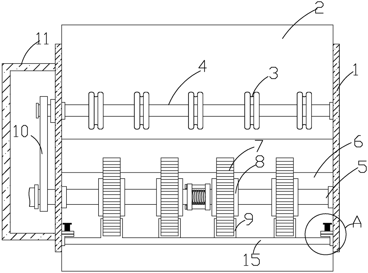
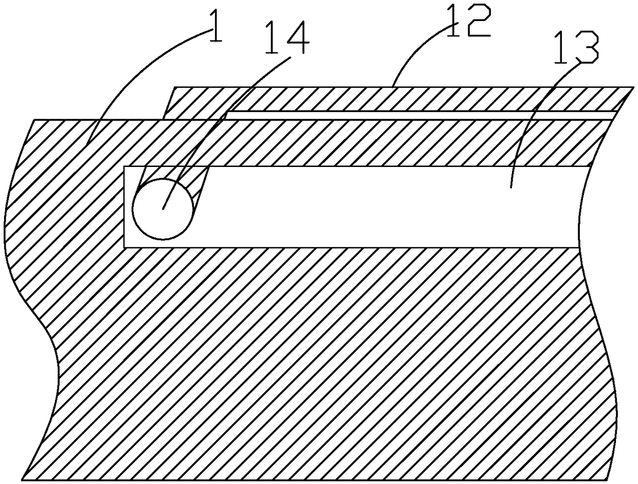
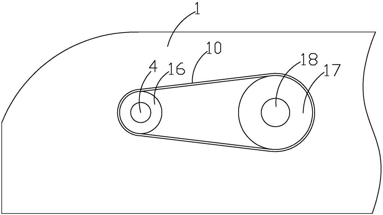
[0028] refer to figure 1...


PUM


Abstract

The invention discloses a money twisting mechanism of a money counting machine, and the mechanism comprises a shell. The front end of the shell of the cash counter is rotatably connected with a moneypassing shaft, a plurality of money passing wheels are interference-fitted on the money passing shaft, a money twisting shaft is rotatably connected between the inner walls of the money counter at a position on one side of the money passing shaft, the money twisting shaft is interference-fitted with a plurality of money twisting wheels, and a connecting mechanism is installed in the middle of themoney twisting shaft. By dragging the twisting shaft close to the drive shaft, the outer retainer ring is driven to slide on the guide rod and press the second spring, so that the distance between thetwo twisting shafts is reduced, so that the banknote twisting shaft adjacent to the drive shaft can be disengaged from the drive shaft, When the twisting ring on the twisting wheel is ground, the twisting shaft can be conveniently removed, so that the replacement of the twisting ring on the twisting wheel becomes convenient, the frictional force of the twisting ring can be maintained, the twisting wheel is not easy to slip with the banknotes, the counting stability is maintained, and the convenience of maintenance of the banknote counter is improved.

Description

technical field [0001] The invention relates to the technical field of banknote counter equipment, in particular to a banknote twisting mechanism of a banknote counter. Background technique [0002] The banknote lowering table is composed of the lower banknote plate, resistance rubber, sliding banknote tongue, sliding banknote plate, adjusting screw, balance device, twisting rubber ring, twisting banknote wheel core, etc., while the resistance rubber, sliding banknote tongue, adjusting screw, twisting banknote The rubber ring will determine whether the banknote is accurate or not. First, ensure that the front edge of the resistance rubber cannot be pitted. If there is a pit, turn the resistance rubber to the opposite side to use or replace new accessories. Before, it will be easy to twist two sheets at once, resulting in inaccurate counting. If it is later, the banknotes will be unsmooth and slow. The adjusting screw will determine the pulling force of the entire banknote lo...

Claims


Application Information

Patent Timeline
Patent Type & Authority Applications(China)
IPC IPC(8): G06M7/06G06M1/02
CPCG06M1/02G06M7/06
Inventor 倪林安
Owner PINGYANG RANPENG ELECTRONICS MACHINERY
Learn More