Electrical connector

An electrical connector and electrical connection technology, applied in the direction of connection, circuit, connecting device components, etc., can solve the problems of elastic arm fatigue, elastic arm short-circuit, complex conductive terminal manufacturing process, etc., to improve transmission capacity, not easy to fatigue , the effect of enhancing elasticity

Active Publication Date: 2018-12-18
DEYI PRECISION ELECTRONIC IND CO LTD PANYU
View PDF3 Cites 6 Cited by
  • Summary
  • Abstract
  • Description
  • Claims
  • Application Information

AI Technical Summary

Problems solved by technology

[0003] Under normal circumstances, in order to achieve a good electrical connection between the conductive terminal and the chip module, it is necessary to have a stable contact between the conductive terminal and the chip module, so it is necessary to increase the elasticity of the elastic arm accordingly. The common design is to make the elastic arm Lengthened to obtain better elasticity, thereby ensuring a stable contact between the conductive terminal and the chip module, but with such a structure, the elastic arm is prone to fatigue during the long-term crimping of the chip module, and the conductive terminal cannot be guaranteed. The stable electrical contact with the chip module cannot effectively reduce the height of the conductive terminals, and it cannot meet the needs of thinning electrical connectors; at the same time, under the trend of increasing density of conductive terminals, longer elastic arms Short circuits are prone to occur between them; in addition, in order to reduce the height of the conductive terminal and ensure that the elastic arm has sufficient elasticity, the longer elastic arm needs to be designed for multiple bending, which makes the process of the conductive terminal very complicated.

Method used


Image

  • Electrical connector
  • Electrical connector
  • Electrical connector

Examples


Embodiment Construction

[0046] In order to facilitate a better understanding of the purpose, structure, features, and effects of the present invention, the present invention will now be further described in conjunction with the accompanying drawings and specific embodiments.

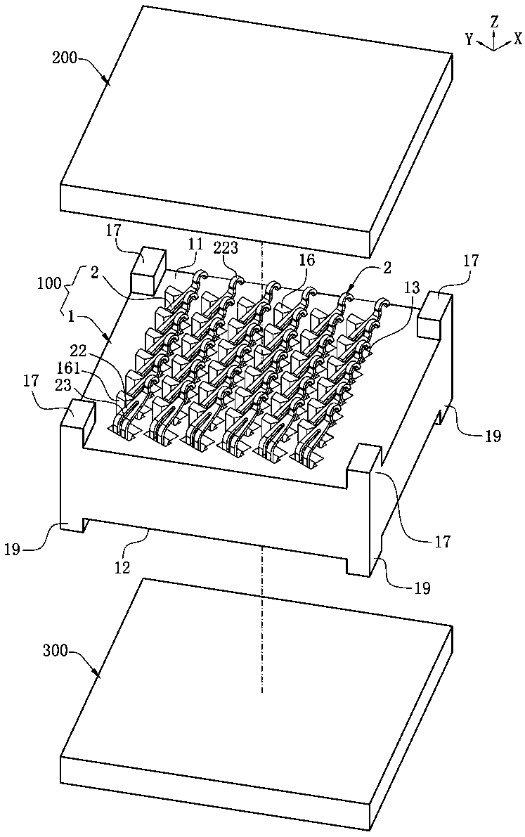
[0047] Such as figure 1 As shown, the electrical connector 100 of the present invention defines a front-rear direction X, a left-right direction Y and a vertical direction Z perpendicular to the front-rear direction X.

[0048] Such as figure 1 As shown, it is an electrical connector 100 according to the first embodiment of the present invention, which is used to electrically connect a chip module 200 to a circuit board 300, which includes a body 1 for carrying the chip module 200 upwards, and is housed in A plurality of terminals 2 of the body 1 .

[0049] Such as figure 1 As shown, in this embodiment, the body 1 is made of insulating material, of course, in other embodiments, the body 1 can also be made of other materials th...


PUM


Abstract

An electrical connector configured to electrically connect to a chip module includes: a body, provided with at least one accommodating hole, where the body has a protruding block provided to protrudeupward from one side of the accommodating hole, and the protruding block is configured to support the chip module upward; and at least one terminal, correspondingly accommodated in the at least one accommodating hole. The terminal includes a base, accommodated in the accommodating hole; an elastic arm, formed by extending forward from the base, located at one side of the protruding block, and configured to be electrically connected with the chip module; and a through slot, running vertically through the elastic arm. The protruding block has a rear end. The base is located behind the rear end,and the through slot extends forward beyond the rear end. On the premise that the length of the elastic arm is not changed, the elastic arm is resistant to fatigue, the electrical connector is thinned, when the chip module is downwards abutted on the elastic arm, two parallel conductive routes are formed on two opposite sides of the elastic arm with respective to the through slot, and thus the high frequency signal transmission performance of the terminal is improved.

Description

technical field [0001] The invention relates to an electrical connector, in particular to an electrical connector electrically connected to a chip module. Background technique [0002] The chip module is usually electrically connected to the circuit board through an electrical connector. The electrical connector has an insulating body and a number of conductive terminals mounted on the insulating body. The conductive terminals have tails connected to the circuit board and connected to the chip module and can be elastic. Deformed arms. With the continuous development of technology, the arrangement density of conductive terminals on the electrical connector is increasing, and at the same time, the height of the electrical connector is also reduced to meet the demand for thinning. [0003] Under normal circumstances, in order to achieve a good electrical connection between the conductive terminal and the chip module, it is necessary to have a stable contact between the conduct...

Claims


Application Information

Patent Timeline
Patent Type & Authority Applications(China)
IPC IPC(8): H01R12/71H01R13/24H01R13/502H01R33/74
CPCH01R12/716H01R13/2414H01R13/2442H01R13/502H01R33/74
Inventor 黄常伟吴永权
Owner DEYI PRECISION ELECTRONIC IND CO LTD PANYU
Why Eureka
Try Eureka