
Multifunctional Cable Trailer

A multi-functional, cable technology, applied in cable laying equipment, motor vehicles, transportation and packaging, etc., can solve the problems of heavy cable weight, cable material aging, waste, etc., and achieve the effect of large supporting area

Inactive Publication Date: 2020-09-01
国网山东省电力公司安丘市供电公司 +1
View PDF6 Cites 0 Cited by
  • Summary
  • Abstract
  • Description
  • Claims
  • Application Information

AI Technical Summary

Problems solved by technology

Based on the characteristics of the cable, during the cable laying process, there are often hidden dangers in the detection and use of the cable due to the aging of the cable itself or accidental damage during storage and transportation.
[0003] In the process of cable laying, the cable needs to be pulled to the designated position, and a large part of the weight of the cable is relatively large, and it is difficult to drag the cable manually. The cable can only be pulled to the designated position by increasing the number of labor, which will inevitably cause personnel injuries. waste, and work time is greatly increased
At this stage, there are more cable conveyors, which are more convenient and fast in construction. However, this type of cable conveyor has great disadvantages in the use process, that is, it cannot be moved, and the cable conveyor cannot be moved during the traction process. Unable to adapt to different grounds for effective fixation, the scope of application is relatively single
[0004] In addition, when it is necessary to pull the cable in the gully, the current cable pulling machinery and equipment cannot realize the pulling of the cable using gullies of various widths.
And the direction of cable pulling is single, and mechanical installation needs to be carried out according to the pulling direction of the cable, which increases the working time of cable pulling

Method used

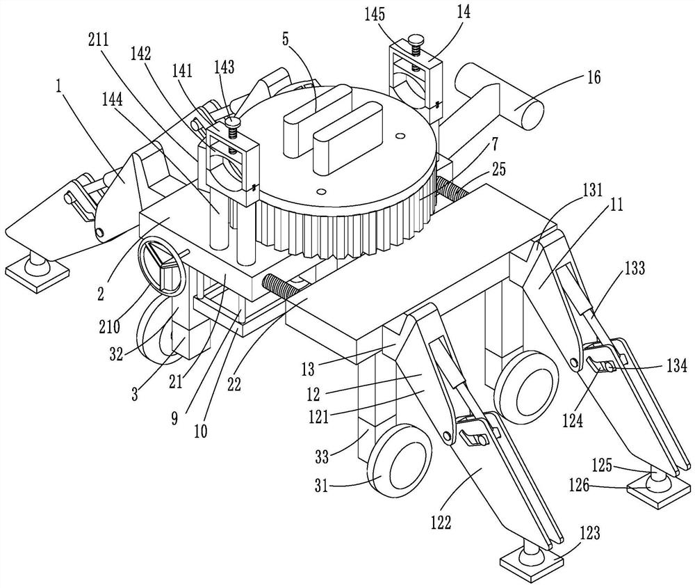
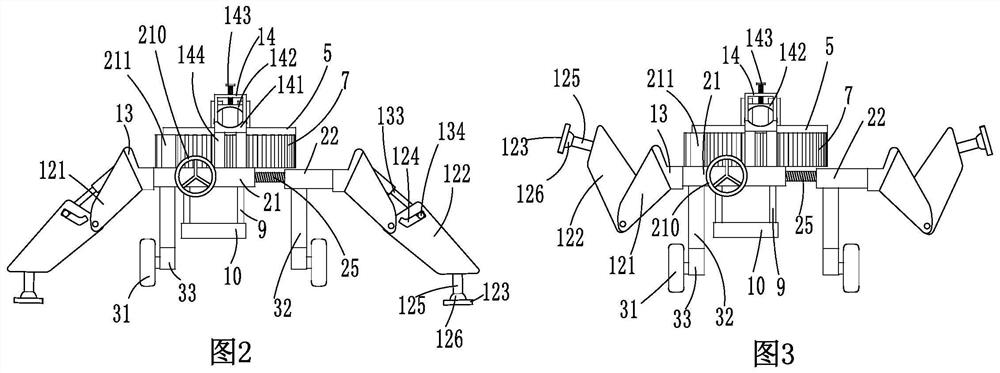
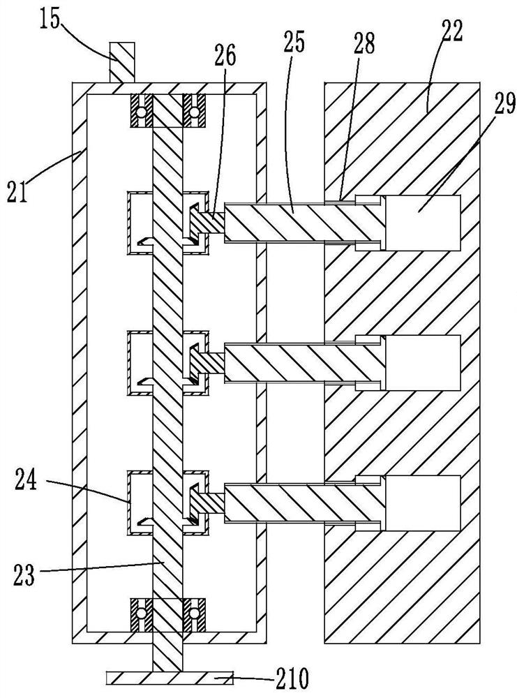

Image

  • Multifunctional Cable Trailer
  • Multifunctional Cable Trailer
  • Multifunctional Cable Trailer

Examples


Embodiment Construction

[0036] In order to understand the present invention better, below in conjunction with appendix Figure 1-10 Embodiments of the present invention will be explained in detail.

[0037] like Figure 1-Figure 3 As shown, the present invention includes a support device 1, a telescopic frame 2, a running device 3 and a clamp 14, and the telescopic frame 2 includes a fixed plate 21 and a movable plate 22, and between the fixed plate 21 and the movable plate 22 The distance between the fixed plate 21 and the movable plate 22 can be freely adjusted according to the width of the ravine when the cable is pulled across the ravine through the connection of the telescopic device.

[0038] like Figure 1-Figure 4As shown, the telescopic device includes a driving shaft 23, several commutators 24 and several threaded rods 25, and more optimally, the number of the commutators 24 and the threaded rods 25 selected by the present invention is three , the fixed plate 21 is provided with the driv...


PUM


Abstract

The invention discloses a multi-functional cable towing vehicle, the actuator comprise a support device, A telescopic frame, a walking device and a clamping device are characterize in that that telescopic frame comprises a fixing plate and a movable plate, wherein the fixing plate and the movable plate are connected with each other through the telescopic device, a rotating disk is connected with the fixing plate through a rotating shaft, and the clamping device comprises a square frame, an arc block, a bolt and two support columns. The cable conveyor can be installed on the invention, and thecable can be directly clamped on the invention. The distance between the movable plate and the fixed plate is adjusted by the function of the telescopic frame to adapt to the different width of the gully topography; The cable conveyor is installed on the rotating disk above the fixed plate, and is no longer restricted by the single traction direction of the cable conveyor through the rotating action of the rotating disk, and the angle can be adjusted freely; The traveling device can make up for the inconvenience of the cable traction machinery in the moving process at this stage.

Description

technical field [0001] The invention relates to a multifunctional cable towing vehicle. Background technique [0002] A cable is made of one or more mutually insulated conductors covered with insulation and protective layers. It is a wire that transmits power or information from one place to another, or a device that uses metal as a medium to transmit signals. Based on the characteristics of the cable, during the cable laying process, there are often hidden dangers in the detection and use of the cable due to the aging of the cable itself or accidental damage during storage and transportation. [0003] In the process of cable laying, the cable needs to be pulled to the designated position, and a large part of the weight of the cable is relatively large, and it is difficult to drag the cable manually. The cable can only be pulled to the designated position by increasing the number of labor, which will inevitably cause personnel injuries. Waste, and work time increases greatl...

Claims


Application Information

Patent Timeline
Patent Type & Authority Patents(China)
IPC IPC(8): H02G1/06B62D57/028
CPCB62D57/028H02G1/06
Inventor 王楠刘强李金莲王志国张晓鹏鞠仕波曹立杰韩晓明赵建鹏张振国王志达
Owner 国网山东省电力公司安丘市供电公司
Learn More