

A method and system for video caching based on cooperation among multi-cache servers
A caching server and server technology, applied in transmission systems, digital transmission systems, electrical components, etc., can solve the problems of multi-system storage space, video storage redundancy, occupancy, etc., and achieve the effect of reducing cache space and improving utilization
- Summary
- Abstract
- Description
- Claims
- Application Information
AI Technical Summary
Problems solved by technology
Method used
Image


Examples
Embodiment 1
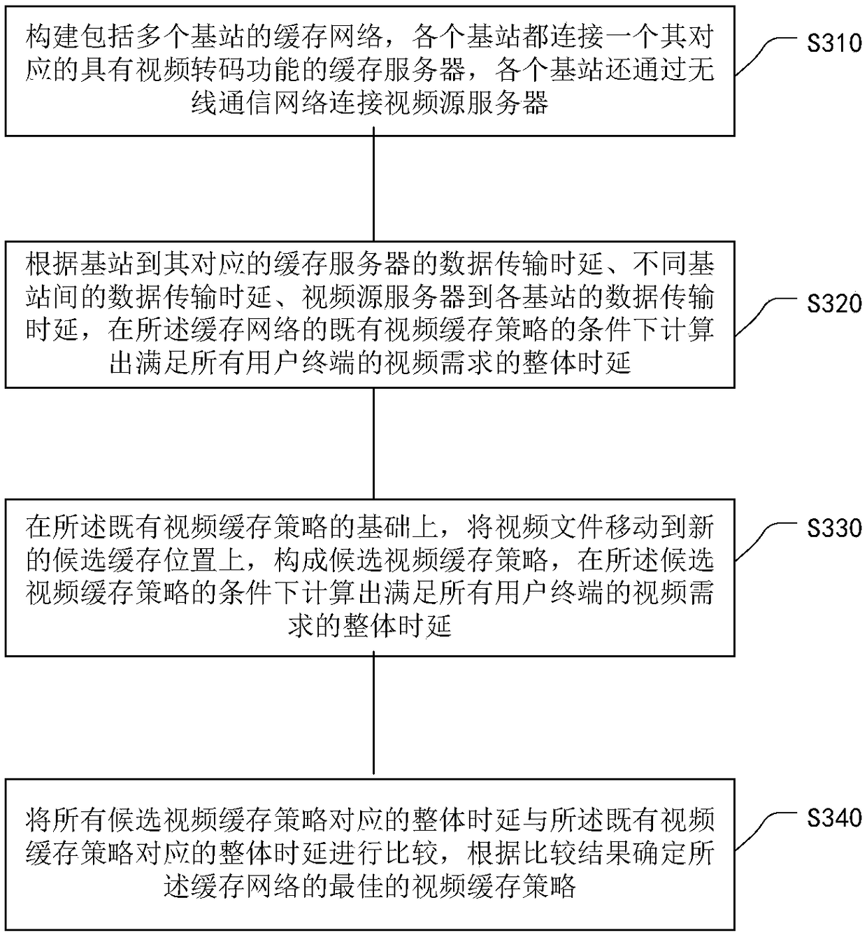
[0050] The processing flow of a video caching method based on cooperation between multiple caching servers provided by this embodiment is as follows: image 3 As shown, the following processing steps are included:
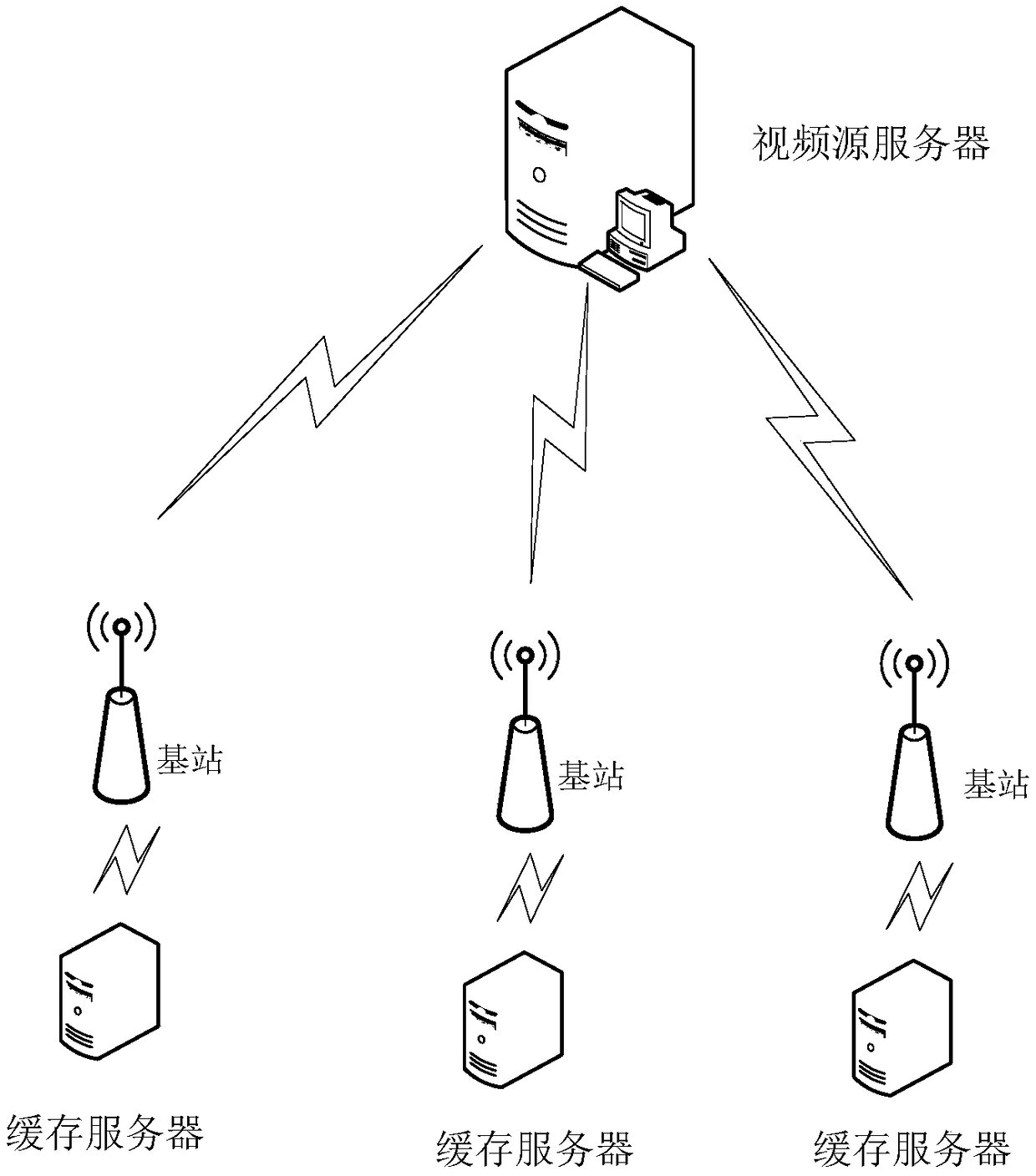
[0051] Step S310, constructing a cache network including multiple base stations, each base station is connected to a corresponding cache server with video transcoding function, and each base station is also connected to a video source server through a wireless communication network.
[0052] Build a caching network including multiple base stations. Each base station is connected to a corresponding caching server with video transcoding function. Each base station uses the corresponding caching server to provide video resources for mobile user terminals in its coverage area. Different base stations communicate with each other. Collaboratively transmit video resources, each base station is also connected to a video source server that stores all video files, the data t...
Embodiment 2
[0058] Figure 4 The processing flowchart of a video transcoding-based caching method based on the cooperation between caching servers provided in this embodiment includes the following processing steps:
[0059] Step 1, initialization. Initialize the existing cache strategy X to be empty, X is the set of each video cache scheme, X={x ki =j|k∈N, i∈V, j∈Q+0}, where when j=0, it means that the video i is not cached in the cache server k, and when j≠0, it means that the cache server k has the video i cached Video version with resolution j. N={1,2,...K} is the collection of cache servers, V={1,2...I} is the collection of videos, Q={1,2...J} is the collection of resolutions; the cache space of each cache server size C k , where k∈N; the unit data transmission delay between any base stations is d kk’ , the unit data transmission delay from the video source server to each base station is d k , the size of the video version (i,j) of video i with resolution j is S ij ; When the ...
PUM
 Abstract
Description
Claims
Application Information