High-temperature disinfection device based on optical fiber laser lamp

A high-temperature disinfection, fiber laser technology, applied in disinfection, water supply equipment, sanitary equipment for toilets, etc., can solve the problems of restricting the effect of disinfection, the rotation of the product, and the inability to cool down the items, so as to improve the disinfection performance and increase the irradiation. the area and the effect of increasing the disinfection effect

Inactive Publication Date: 2018-12-21
苏州高新区建金建智能科技有限公司
View PDF4 Cites 0 Cited by
  • Summary
  • Abstract
  • Description
  • Claims
  • Application Information

AI Technical Summary

Problems solved by technology

[0002] With the rapid development of social science and technology, more and more machinery and equipment appear around our lives, especially in the rapid development of technology in various industries, in some special industries such as medical treatment, food testing and food processing, etc. The non-disposable utensils used in the industry must be sterilized after use before they can be reused, which has led to the emergence of disinfection equipment. However, the existing high-temperature disinfection devices do not use the high temperature generated by laser lamps. Disinfection, at the same time, the existing high-temperature disinfection device can not make the object record rotation during disinfection, thereby greatly limiting the effect of disinfection. On the one hand, the existing high-temperature disinfection device only performs one-time disinfection, and the disinfection performance is not comprehensive, and cannot cool down the items. On the other hand, the existing high-temperature disinfection device cannot preheat the items before disinfection, which greatly increases the time required for disinfection, and greatly The work efficiency of the user is reduced, so the present invention proposes a high-temperature disinfection device based on an optical fiber laser lamp

Method used


Image

  • High-temperature disinfection device based on optical fiber laser lamp
  • High-temperature disinfection device based on optical fiber laser lamp
  • High-temperature disinfection device based on optical fiber laser lamp

Examples


Embodiment approach

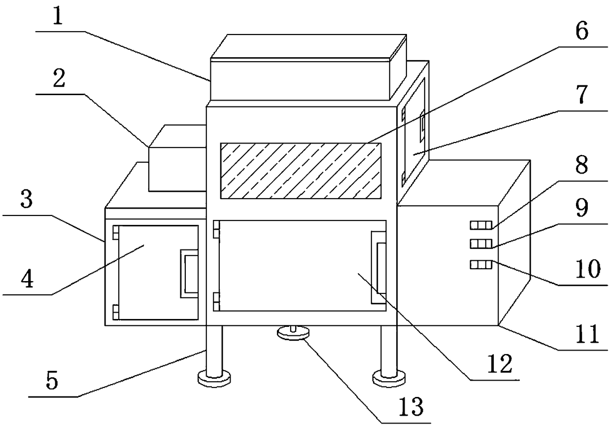
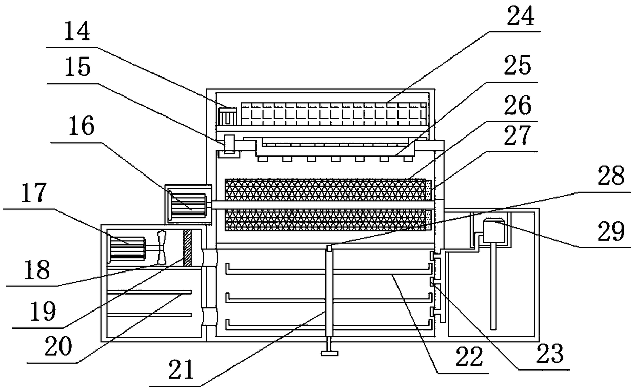
[0026] As a preferred embodiment of the present invention, the suction port of the water pump 29 is connected to the disinfection water tank 11 through the first water pipe, and the water outlet of the water pump 29 is connected to the nozzle 23 through the second water pipe.

[0027] As a preferred embodiment of the present invention, the disinfection water tank 11 is filled with disinfectant, and the fiber laser lamp 25 is an infrared laser lamp.

[0028]As a preferred embodiment of the present invention, the second motor 17 is welded on the inner side wall of the preheating box 3 through the second motor base, and the fan blade 18 is welded on the output shaft of the second motor 17 .

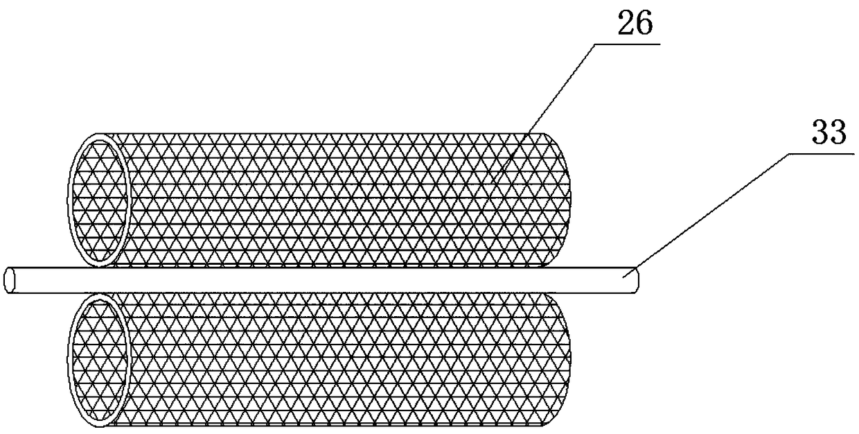
[0029] As a preferred embodiment of the present invention, a through hole I is opened in the connection area between the motor box-2 and the housing 1 , and the output shaft of the motor-16 passes through the through hole and is welded to one end of the rotating rod 33 .

[0030] As a prefer...


PUM


Abstract

The invention provides a high-temperature disinfection device based on an optical fiber laser lamp. The device comprises a smart system and a housing, wherein the smart system comprises a control panel, a timer, a temperature sensor and a display screen; a mounting groove 1 is formed on one side of the housing, and a door plate 3 is connected to the inner side wall of the mounting groove 1 througha hinge 3; a disinfection water tank is welded on one side of the housing; 3 mounting grooves 2 are formed on the front side of the disinfection water tank, and an air-drying button, a spraying button and a disinfection button are respectively connected to the inner side walls of the mounting grooves 2 through screws; and a motor box 2 is welded on one inner side wall of the disinfection water tank, and a water suction pump is connected to one inner side wall of the motor box 2 through a motor base 3. The high-temperature disinfection device based on the optical fiber laser lamp is novel in design, has multiple functions, and is capable of disinfecting objects effectively.

Description

technical field [0001] The invention is a high-temperature disinfection device based on an optical fiber laser lamp, which belongs to the technical field related to high-temperature disinfection. Background technique [0002] With the rapid development of social science and technology, more and more machinery and equipment appear around our lives, especially in the rapid development of technology in various industries, in some special industries such as medical treatment, food testing and food processing, etc. The non-disposable utensils used in the industry must be sterilized after use before they can be reused, which has led to the emergence of disinfection equipment. However, the existing high-temperature disinfection devices do not use the high temperature generated by laser lamps. Disinfection, at the same time, the existing high-temperature disinfection device can not make the object record rotation during disinfection, thereby greatly limiting the effect of disinfecti...

Claims


Application Information

Patent Timeline
IPC IPC(8): A61L2/08A61L2/18A61L2/26
CPCA61L2/085A61L2/18A61L2/26
Inventor 张秀平
Owner 苏州高新区建金建智能科技有限公司
Why Eureka
Try Eureka