
Multifunctional physical laboratory test bench

A multi-functional physics and laboratory technology, applied in the field of multi-functional physics laboratory test bench, can solve the problems of not being able to store and protect the physical experiment equipment, not being able to meet the needs of use well, and not being able to move anytime and anywhere, etc., to achieve a fixed effect Good, convenient and efficient to operate, and reduce the experimental burden

Inactive Publication Date: 2018-12-21
HENAN UNIV OF SCI & TECH
View PDF6 Cites 2 Cited by
  • Summary
  • Abstract
  • Description
  • Claims
  • Application Information

AI Technical Summary

Problems solved by technology

The physics experiment table is made of general-purpose technology and process, which can only meet the teaching of teachers and the subject experiment of students in the physics laboratory or fixed place. However, the physics experiments of different subjects require different experimental equipment and test benches. , which needs to occupy a lot of space and consume a lot of materials to meet various experimental requirements, which is very troublesome, and it is easy to damage the equipment during specific operations
When the experimental device needs to be changed and adjusted, the existing experimental bench is rigid and cannot be adjusted flexibly and effectively according to actual needs
[0003] In addition, most of the current physical experiment devices for students are inconvenient to carry. They can only be used as fixed workbenches and cannot be moved anytime and anywhere, which cannot meet the needs of use well.
Moreover, the problem of special storage tools is not solved, which makes it very inconvenient for students to do experiments, and it is impossible to preserve and protect the physical experiment equipment well.

Method used


Image

  • Multifunctional physical laboratory test bench
  • Multifunctional physical laboratory test bench
  • Multifunctional physical laboratory test bench

Examples


Embodiment Construction

[0026] Specific examples are given below to further describe the technical solution of the present invention in a clear, complete and detailed manner. This embodiment is the best embodiment on the premise of the technical solution of the present invention, but the protection scope of the present invention is not limited to the following embodiments.

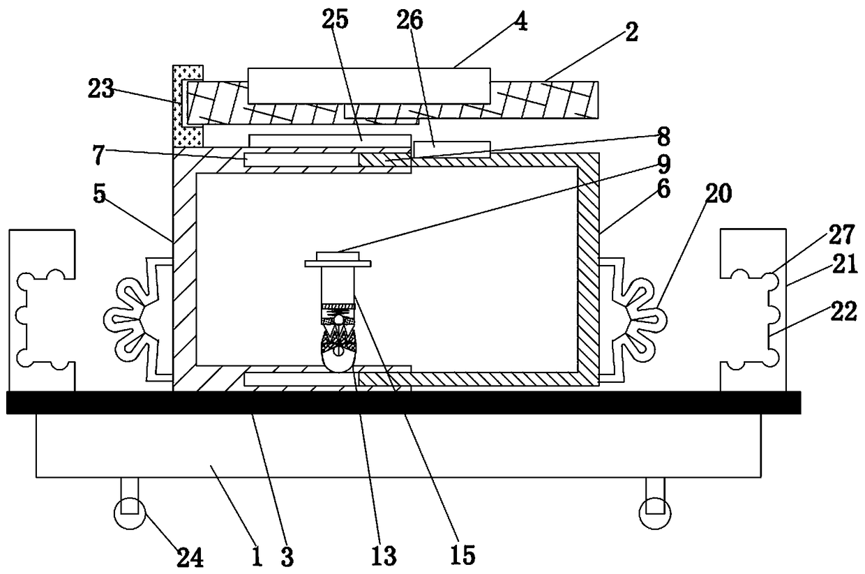
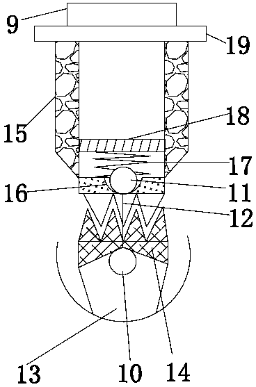
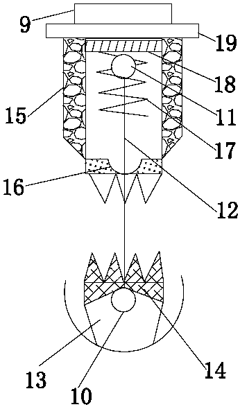
[0027] Such as figure 1 As shown, a multifunctional physical laboratory test bench includes a base 1, a telescopic workbench 2, a cabinet device that is slid on the base 1 through a guide rail 3 and is spaced apart from the telescopic workbench 2 above, and the cabinet device An outlet mechanism is provided on the upper end surface, and an opening 4 corresponding to the outlet mechanism is provided on the telescopic workbench 2. The cabinet device includes a left cabinet body 5 and a right cabinet body 6 matched with the opening, and the right side of the left cabinet body 5 The end face of the opening is an annular groove struc...


PUM


Abstract

The invention discloses a multifunctional physical laboratory test bench. The multifunctional physical laboratory test bench comprises a base, a telescopic workbench, a cabinet body device which is arranged on the base in a sliding manner and is spaced from the upper telescopic workbench; the cabinet body device comprises a left cabinet body and a right cabinet of which openings are matched, and is internally provided with an experimental device; the experimental device comprises an emitter, an elastic mechanism and an experimental mechanism which are sequentially connected; one limiting device is arranged on each of two sides of the outer part of the cabinet body device; the limiting devices comprise a plurality of cut-in strips on outer walls of the two sides of the cabinet body device,and embedded plates located on two sides of the cabinet body device and arranged at two ends of the guide rails. The multifunctional physical laboratory test bench disclosed by the invention has the advantages of novel design, convenience and efficiency in operation, good storage effect, high protectiveness and capability of being adjusted and moved according to actual needs; the multifunctional physical laboratory test bench is suitable for environmental requirements of different physical experiments, so that the experimental burden is reduced and the service life is prolonged.

Description

technical field [0001] The invention relates to the professional technical field of physics, and more specifically relates to a multifunctional physics laboratory test bench. Background technique [0002] As we all know, in the process of students learning physics, physics experiment is an indispensable teaching link. Physics experiments are helpful to students' understanding of physics knowledge, and can effectively improve students' learning interest and hands-on ability in physics. The physics experiment table is made of general-purpose technology and process, which can only meet the teaching of teachers and the subject experiment of students in the physics laboratory or fixed place. However, the physics experiments of different subjects require different experimental equipment and test benches. , which needs to occupy a lot of space and consume a lot of materials to meet various experimental requirements, which is very troublesome, and it is easy to damage the equipment...

Claims


Application Information

Patent Timeline
IPC IPC(8): B01L9/02B01L7/00B01L1/00
CPCB01L1/00B01L7/00B01L9/02
Inventor 郝希平雷茂生
Owner HENAN UNIV OF SCI & TECH
Learn More