Workpiece conveying and screening equipment

A technology for screening equipment and workpieces, which is applied in the field of workpiece conveying and screening equipment, can solve problems such as affecting work efficiency, slow screening speed of roller shafts, affecting screening efficiency, etc., and achieves a good cleaning effect.

Active Publication Date: 2018-12-21
合肥九州龙腾科技成果转化有限公司
View PDF8 Cites 6 Cited by
  • Summary
  • Abstract
  • Description
  • Claims
  • Application Information

AI Technical Summary

Problems solved by technology

[0002] The roller shaft refers to the cylindrical part that can roll on the machine. During the production and processing process, the roller shaft is first cooled and shaped at high temperature, and then its surface is polished. Finally, the polished roller shafts of different specifications are packaged separately; however, in the packaging In the past, it was necessary to sieve rollers of the same length and different sizes for better packaging, because before sieving, the rollers have just been polished, and there will still be grinding on the su

Method used


Image

  • Workpiece conveying and screening equipment
  • Workpiece conveying and screening equipment
  • Workpiece conveying and screening equipment

Examples


Embodiment Construction

[0021] The following is further described in detail through specific implementation methods:

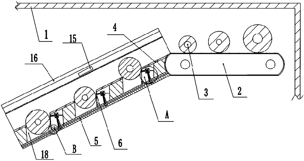
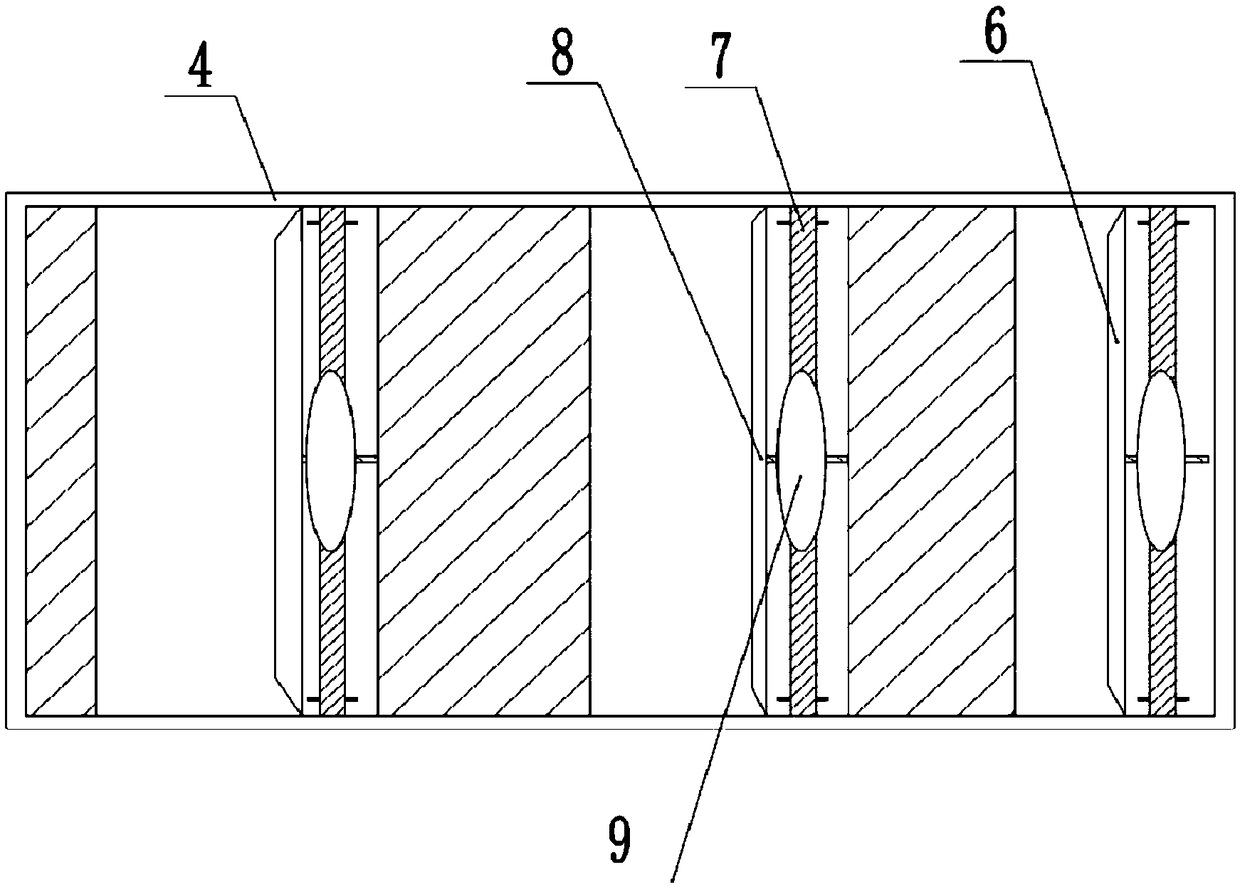
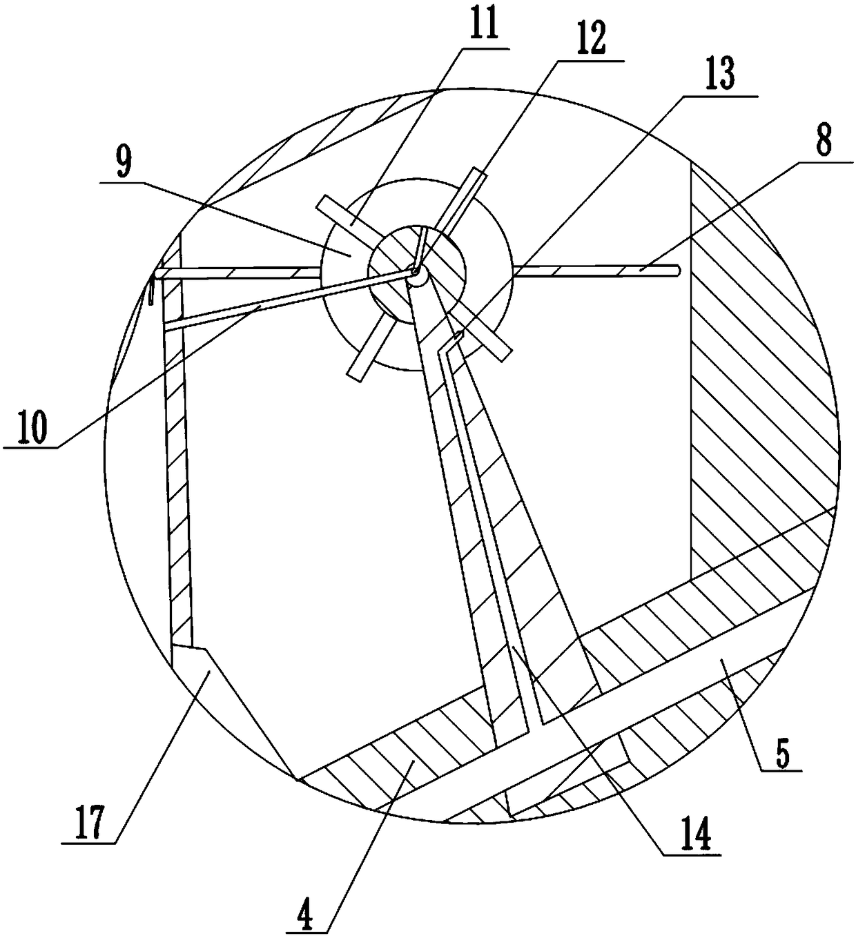
[0022] The reference signs in the drawings of the description include: frame 1, conveyor belt 2, roller shaft 3, screening plate 4, air channel 5, movable plate 6, rotating shaft 7, pole 8, elastic air bag 9, hose 10, fan Leaf 11, first passage 12, air nozzle 13, second passage 14, negative pressure fan 15, negative pressure chamber 16, air pipe 17, screening tank 18.

[0023] Such as figure 1 and figure 2 As shown, the workpiece conveying and screening equipment includes a frame 1, a conveyor belt 2 installed on the frame 1, and a screening plate 4 arranged obliquely at the left end of the conveyor belt 2; the screening plate 4 is fixedly connected with the frame 1, and the screening plate 4 is provided with There are three screening slots 18, and the opening sizes of the three screening slots 18 increase sequentially from top to bottom. A movable plate 6 is hinged at the bottom ...


PUM


Abstract

The invention relates to the field of sorting equipment, in particular to workpiece conveying and screening equipment. The workpiece conveying and screening equipment comprises a frame, a conveying belt, a screening plate, a collecting box and a rotating shaft; multiple screening grooves are formed in the screening plate; notches of the screening grooves are hinged with movable plates; first through holes are formed in the groove walls of the screening grooves, and are positioned under the movable plates; the rotating shaft is rotationally connected with the frame; a first channel is formed inthe rotating shaft; an airbag sleeves the middle part of the rotating shaft, and is tightly connected with the surface of the rotating shaft; a support rod is mounted on the surface of the airbag; asecond through hole is formed in the airbag; a hose is hinged to the tail end of the first channel, and is fixedly connected with the first through holes on the screening plate; an air way is mountedunder the collecting box; and an air pipe is connected between the air way and the collecting box. The workpiece conveying and screening equipment can prevent roller shafts with the same lengths and different diameters from blocking screening channels in the screening process, and can remove residues attached on the roller shafts.

Description

technical field [0001] The invention relates to the field of sorting equipment, in particular to workpiece conveying and screening equipment. Background technique [0002] The roller shaft refers to the cylindrical part that can roll on the machine. During the production and processing process, the roller shaft is first cooled and shaped at high temperature, and then its surface is polished. Finally, the polished roller shafts of different specifications are packaged separately; however, in the packaging In the past, it was necessary to sieve rollers of the same length and different sizes for better packaging, because before sieving, the rollers have just been polished, and there will still be grinding on the surface of the rollers during the process of conveying and sieving. The remaining debris and other residues will affect the efficiency of screening, and the diameter of the rollers during the conveying and screening process is very small. The roller with a slightly larg...

Claims


Application Information

Patent Timeline
IPC IPC(8): B07B13/07B07B13/16B07B13/14B08B5/02
CPCB07B13/07B07B13/14B07B13/16B08B5/02
Inventor 曾雨琳詹华山李涛黄诗鸿张小恒袁苗达
Owner 合肥九州龙腾科技成果转化有限公司
Why Eureka
Try Eureka