Intelligent image processing method and device

A processing method and intelligent image technology, applied in the field of image processing, can solve the problems of affecting the quality of photo frame preparation, the speed of preparation, affecting the production and processing efficiency of photo frames, and the inconvenience of adjusting the direction of rotation of the drill bit, so as to achieve simple and convenient drilling steps and simple and convenient adjustment steps , Reduce the effect of manual operation steps

Inactive Publication Date: 2018-12-21
广州同轩信息科技有限公司
View PDF0 Cites 0 Cited by
  • Summary
  • Abstract
  • Description
  • Claims
  • Application Information

AI Technical Summary

Problems solved by technology

[0002] After the image and photo are printed, they usually need to be installed in the photo frame. During the production and processing of the photo frame, the punching of the photo frame in the prior art mainly depends on manual adjustment and replacement of the drill bit. The use efficiency is low. When the drill bit needs to be replaced repeatedly, it needs to be disassembled repeatedly. This greatly affects the quality and speed of photo frame preparation, and the traditional punching equipment is not convenient to adjust the direction of rotation of the drill bit. Therefore, the punching has strong limitations and is inconvenient to use, which affects the production and processing efficiency of the photo frame. It needs to be improved.

Method used


Image

  • Intelligent image processing method and device
  • Intelligent image processing method and device
  • Intelligent image processing method and device

Examples


Embodiment Construction

[0014] Combine below Figure 1-3 The present invention will be described in detail.

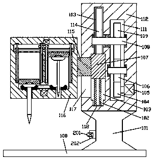
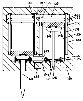
[0015] refer to Figure 1-3 , an intelligent image processing method and device according to an embodiment of the present invention, comprising a base 100, a pillar 101 is fixed on the top end of the base 100, a fixing frame 112 is fixed on the top end of the pillar 101, the mounting The left end of the fixed frame 112 is provided with a processing seat 116, and the bottom end surface of the processing seat 116 is provided with a first piercing cavity 124 symmetrically left and right, and a debugging cavity 129 is provided extending up and down in the top wall of the first piercing cavity 124, so The bottom wall of the debugging cavity 129 is rotated and installed with a conical frame 126, and the outer periphery of the conical frame 126 is fixed with a toothed ring 127, and the upper and lower sides of the conical frame 126 are provided with a ring opposite to the first through cavity 124. ...


PUM


Abstract

The invention discloses an intelligent image processing method and device. The intelligent image processing device comprises a base, wherein a supporting column is fixedly arranged on the top end surface of the base; an aligning frame is fixedly arranged on the top end surface of the supporting column; a processing seat is arranged at the left side end of the aligning frame; first penetrating cavities which are in bilateral symmetry are formed in the bottom end surface of the processing seat; a debugging cavity which extends up and down is formed in the inner top wall of each first penetratingcavity; a pyramidal frame is mounted on the bottom wall of each debugging cavity in a rotating fit manner; a tooth-shaped ring is fixedly arranged on the periphery of each pyramidal frame; each second penetrating cavity which is opposite to the corresponding first penetrating cavity is formed in the corresponding pyramidal frame in an up and down penetrating manner; a debugging frame is mounted in each debugging cavity in a sliding fit manner; each pyramidal wheel which is mutually meshed with the corresponding pyramidal frame is mounted at the bottom end of the corresponding debugging framein the rotating fit manner; a drilling head is fixedly mounted on the bottom end surface of each pyramidal wheel, and penetrates through the corresponding second penetrating cavity and the corresponding first penetrating cavity; and a through groove communicates with the bottom ends of the debugging cavities on the left side and the right side.

Description

technical field [0001] The invention relates to the technical field of image processing, in particular to an intelligent image processing method and device. Background technique [0002] After the image and photo are printed, they usually need to be installed in the photo frame. During the production and processing of the photo frame, the punching of the photo frame in the prior art mainly depends on manual adjustment and replacement of the drill bit. The use efficiency is low. When the drill bit needs to be replaced repeatedly, it needs to be disassembled repeatedly. This greatly affects the quality and speed of photo frame preparation, and the traditional punching equipment is inconvenient to adjust the rotation direction of the drill bit. Therefore, the punching has strong limitations and is inconvenient to use, which affects the production and processing efficiency of the photo frame and needs to be improved. Contents of the invention [0003] The object of the present...

Claims


Application Information

Patent Timeline
Patent Type & Authority Applications(China)
IPC IPC(8): B23B39/16B23B41/00B23B47/26
CPCB23B41/00B23B39/161B23B47/26
Inventor 林柱坚
Owner 广州同轩信息科技有限公司
Why Eureka
Try Eureka