
Novel plastic cutting equipment

A new type of plastic technology, applied in the direction of welding/cutting auxiliary equipment, welding equipment, welding equipment, etc., can solve the problems of short plastic cutting, unable to advance the normal distance, position deviation, etc., and achieve the effect of uniform transmission

Inactive Publication Date: 2018-12-21
董芬芳
View PDF0 Cites 3 Cited by
  • Summary
  • Abstract
  • Description
  • Claims
  • Application Information

AI Technical Summary

Problems solved by technology

[0003] 1. When the plastic cutting equipment cuts the plastic in sections, it needs to cut multiple times, but after each cutting, the cut plastic product cannot be moved away from the place, causing the cut plastic product to be pushed near the cutting edge. Affects the advance of the plastic, unable to advance the normal distance, causing the plastic to be cut too short
[0004] 2. The size of plastic raw materials is divided into different sizes. During the cutting process of plastic cutting equipment, huge vibration potential energy is generated due to strong cutting. The plastic propulsion mechanism is not very effective in fixing and stabilizing plastics of different sizes. Position offset occurs during the cutting process, resulting in cutting errors

Method used


Image

  • Novel plastic cutting equipment
  • Novel plastic cutting equipment
  • Novel plastic cutting equipment

Examples


Embodiment

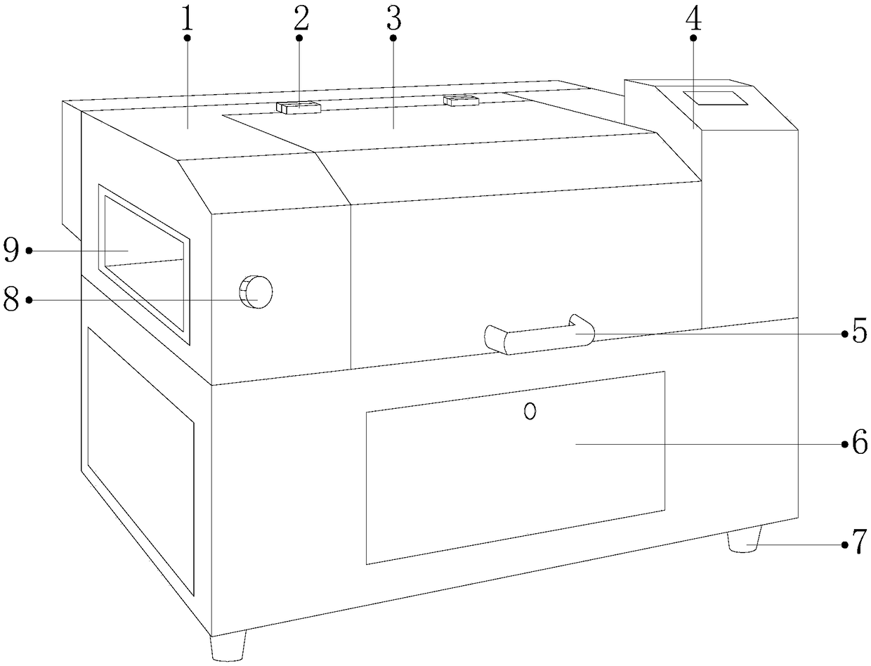
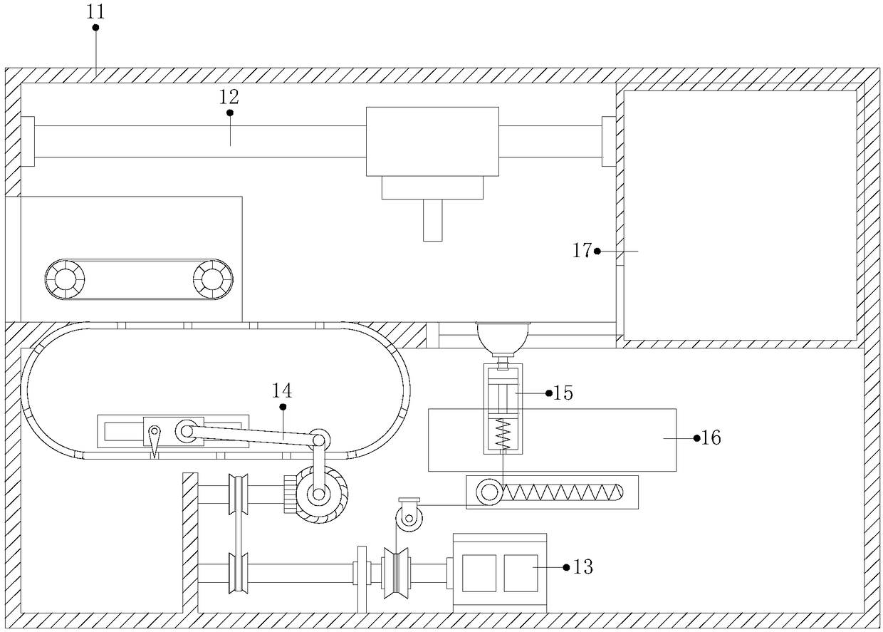
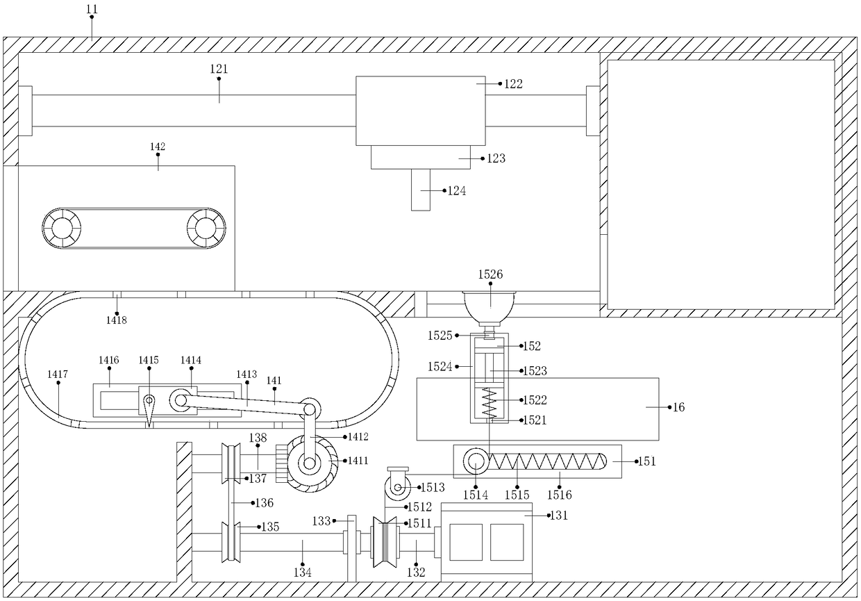
[0027] see Figure 1-Figure 5 , The present invention provides a new type of plastic cutting equipment, the structure includes a cutting host 1, a hinge 2, a box door 3, a control box 4, a handle 5, a maintenance door 6, a support foot 7, an adjustment button 8, and a feeding port 9. The cutting host 1 The top is welded with the hinge 2, the hinge 2 is welded with the box door 3, the cutting host 1 is hinged with the box door 3 through the hinge 2, and the control box 4 is fixedly installed on the top of the cutting host 1 and is electrically connected through wires. Connection, the handle 5 is arranged on the box door 3, the maintenance door 6 is installed on the bottom end of the cutting main machine 1, the supporting feet 7 are provided with four and are fixedly installed at the bottom four corners of the cutting main machine 1, the adjustment button 8 is embedded in the front surface of the cutting main machine 1 and adopts clearance fit. The feeding port 9 is provided on ...


PUM


Abstract

The invention discloses novel plastic cutting equipment. The novel plastic cutting equipment structurally comprises a cutting main machine, hinges, a box door, a control box, a handle, a maintenance door, supporting legs, an adjusting button and a feeding opening. The top end of the cutting main machine and the hinges are welded. The hinges and the box door are welded. The cutting main machine ishinged to the box door through the hinges. The control box is fixedly mounted at the top end of the cutting main machine and is electrically connected with the cutting main machine through a wire. Thehandle is arranged on the box door. The maintenance door is mounted at the bottom end of the cutting main machine. Through a size adjusting mechanism, plastic of different sizes can be reinforced, and conveying is more stable; meanwhile, through cooperation with an air pressure suction cup mechanism, the head ends and the tail ends of the plastic are reinforced, the situation that violent vibration happens in the cutting process, consequently, cutting positions shift, and the cutting positions are wrong is avoided; and the cut plastic moves through a translation mechanism to be away from a cutting mechanism, it is ensured that the plastic can be pushed by a normal distance during cutting of next time, and the plastic is prevented from being cut too short.

Description

technical field [0001] The invention relates to the field of novel cutting plastic equipment, in particular to a novel cutting plastic equipment. Background technique [0002] At present, the application of manual and semi-automatic cutting in my country's manufacturing industry is still relatively common. The requirements for efficiency are also constantly improving. Cutting plastic equipment is used for cutting plastics. However, the current new cutting plastic equipment has the following disadvantages: [0003] 1. When the plastic cutting equipment cuts the plastic in sections, it needs to cut multiple times, but after each cutting, the cut plastic product cannot be moved away from the place, causing the cut plastic product to be pushed near the cutting opening. Affecting the advancement of plastic, unable to advance the normal distance, resulting in too short plastic cutting. [0004] 2. The size of plastic raw materials is divided into different sizes. During the cutt...

Claims


Application Information

Patent Timeline
Patent Type & Authority Applications(China)
IPC IPC(8): B23K26/38B23K26/402B23K26/70B23K37/04
CPCB23K26/38B23K26/402B23K26/702B23K37/0435
Inventor 董芬芳
Owner 董芬芳
Learn More