
Mechanical positioning device for corner connecting pipe welding

A technology of mechanical positioning and mounting holes, applied in the mechanical field, can solve problems such as inaccurate positioning, easy flipping, and positioning range constraints, and achieve the effects of reasonable structure setting, saving production costs, and expanding the scope of application

Inactive Publication Date: 2018-12-21
新昌县奔力机械有限公司
View PDF0 Cites 6 Cited by
  • Summary
  • Abstract
  • Description
  • Claims
  • Application Information

AI Technical Summary

Problems solved by technology

[0003] 1. When the pipe is large and heavy, it is easy to turn over during welding positioning, resulting in inaccurate positioning;
[0004] 2. Although specific positioning tooling can improve the positioning accuracy of angle welding to a certain extent, it is used in pairs after all, so it cannot be quantified and promoted. Compared with a wide variety of pipeline welding products, its positioning range is severely restricted, so in In the welding of various pipes, the cost of welding positioning will be increased

Method used


Image

  • Mechanical positioning device for corner connecting pipe welding
  • Mechanical positioning device for corner connecting pipe welding
  • Mechanical positioning device for corner connecting pipe welding

Examples


Embodiment Construction

[0025] The following will clearly and completely describe the technical solutions in the embodiments of the present invention with reference to the accompanying drawings in the embodiments of the present invention. Obviously, the described embodiments are only some, not all, embodiments of the present invention. Based on the embodiments of the present invention, all other embodiments obtained by persons of ordinary skill in the art without making creative efforts belong to the protection scope of the present invention.

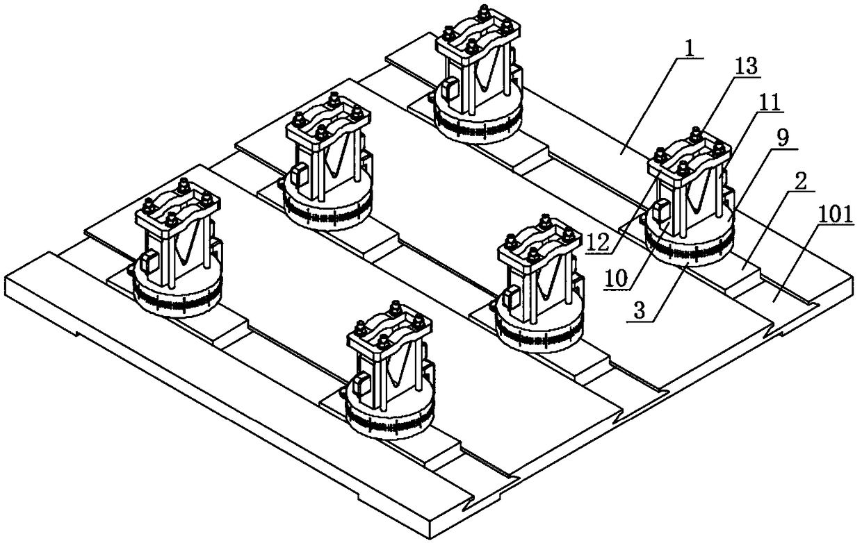
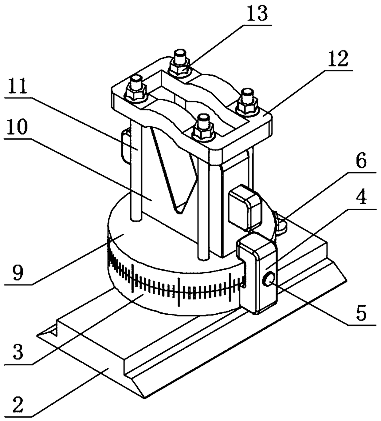
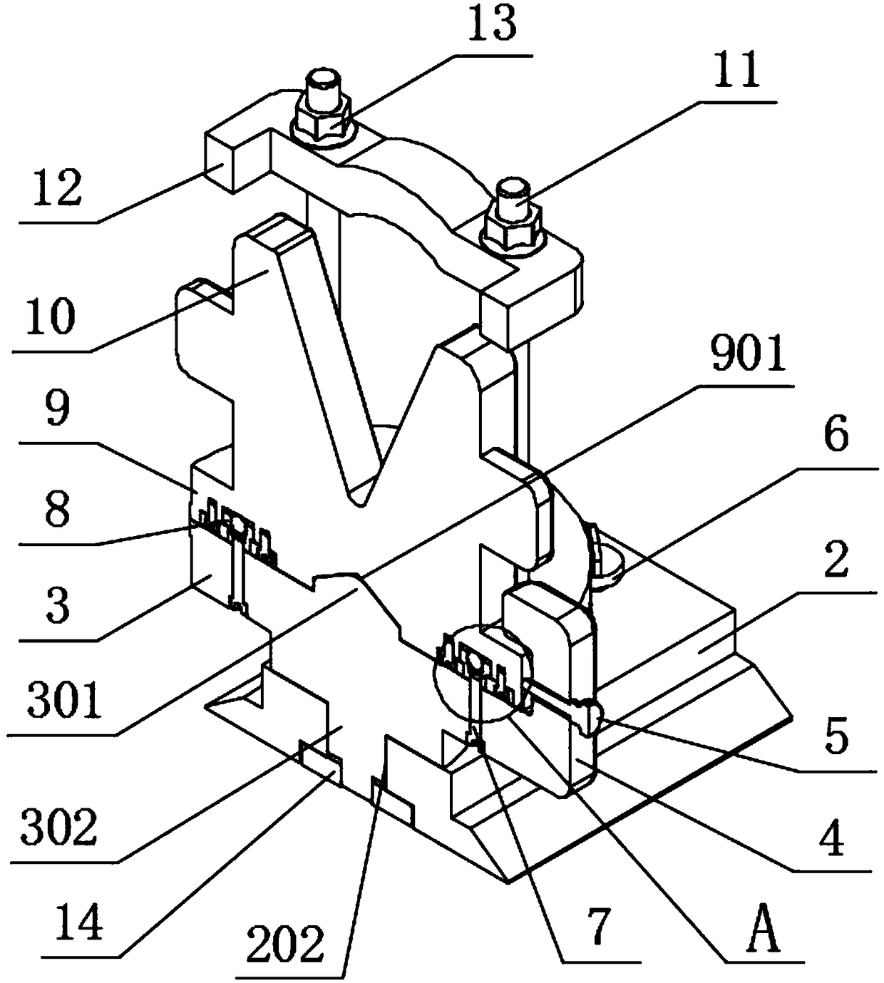
[0026] see Figure 1 to Figure 6 , the present invention provides a technical solution: a mechanical positioning device for corner joint welding, including a support base plate 1 and a rotating clamping seat on which the upper end of the support base plate 1 slides. The main body of the support base plate 1 is a square plate structure, and The upper end surface of the support base 1 is uniformly provided with chute 101 with a dovetail groove structure, and the...


PUM


Abstract

The invention discloses a mechanical positioning device for corner connecting pipe welding. The mechanical positioning device comprises a supporting bottom plate and rotating clamping bases which areconnected with the upper end of the supporting bottom plate in a sliding fit mode, a main body of the supporting bottom plate is of a square plate-shaped structure, sliding grooves in a dovetail groove structure are uniformly distributed on the upper end surface of the supporting bottom plate, the rotating clamping bases are arranged in the sliding grooves in a sliding fit mode, and sliding baseswhich are matched with the sliding grooves and are in a plate-shaped structure are arranged at the lower ends of the rotating clamping bases. According to the device, pressing plates are used for pressing pipelines into V-shaped grooves in clamping bases through nuts which are screwed on locking guide rods, so that the pipelines cannot be turned over in the welding process; and the positions of the rotating clamping bases at the upper end of the supporting bottom plate is adjusted, supporting distance of the welding pipeline is adjusted, relative rotation angles of lower rotating discs and theupper rotating discs are further adjusted, the positioning angles of the welding pipeline are adjusted, so that the device can be used for pipeline welding and positioning of various size specifications, the application range of the positioning device is greatly enlarged, and the production cost is saved.

Description

technical field [0001] The invention relates to the field of mechanical technology, in particular to a mechanical positioning device for corner joint welding. Background technique [0002] In the large-scale pipeline welding process, when it comes to angle welding, a specific positioning device is generally made to improve the angle positioning accuracy of angle welding, but it still has the following disadvantages in actual use: [0003] 1. When the pipe is large and heavy, it is easy to turn over during welding positioning, resulting in inaccurate positioning; [0004] 2. Although specific positioning tooling can improve the positioning accuracy of angle welding to a certain extent, it is used in pairs after all, so it cannot be quantified and promoted. Compared with a wide variety of pipeline welding products, its positioning range is severely restricted, so in In the welding of various pipes, the cost of welding positioning will be increased. Contents of the invention...

Claims


Application Information

Patent Timeline
Patent Type & Authority Applications(China)
IPC IPC(8): B23K37/053
CPCB23K37/0533
Inventor 吴朝阳石三平
Owner 新昌县奔力机械有限公司
Learn More