
Peripheral clamping mechanism and operation method

A technology of clamping mechanism and operation method, which is applied in the direction of clamping, metal processing machinery parts, support, etc., can solve the problems of high difficulty in manipulation, uneven clamping force around, inconsistent running speed of clamping blocks, etc., and achieve the goal of operation Simple control, equal clamping force around and consistent running speed

Active Publication Date: 2018-12-21
上海莘翔自动化科技有限公司
View PDF11 Cites 2 Cited by
  • Summary
  • Abstract
  • Description
  • Claims
  • Application Information

AI Technical Summary

Problems solved by technology

[0004] However, after analysis, it is found that the existing four-sided clamping mechanism has the following deficiencies: one: high difficulty in manipulation, two: different clamping forces around the four sides;

Method used


Image

  • Peripheral clamping mechanism and operation method
  • Peripheral clamping mechanism and operation method
  • Peripheral clamping mechanism and operation method

Examples


Embodiment Construction

[0019] The following will be combined with Figure 1-Figure 2 The present invention is described in detail, and the technical solutions in the embodiments of the present invention are clearly and completely described. Apparently, the described embodiments are only some of the embodiments of the present invention, not all of them. Based on the embodiments of the present invention, all other embodiments obtained by persons of ordinary skill in the art without making creative efforts belong to the protection scope of the present invention.

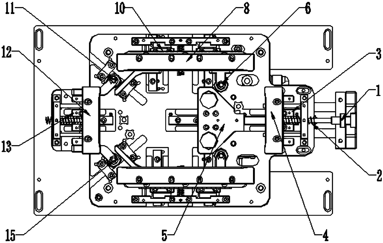
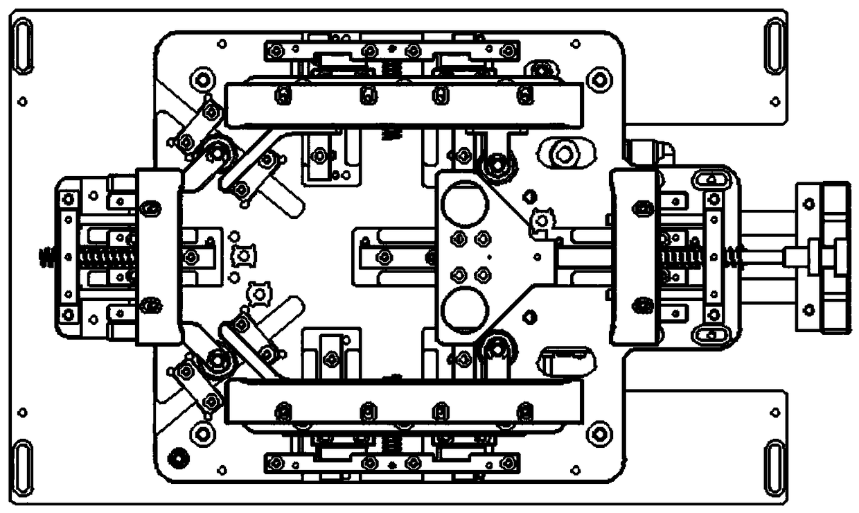
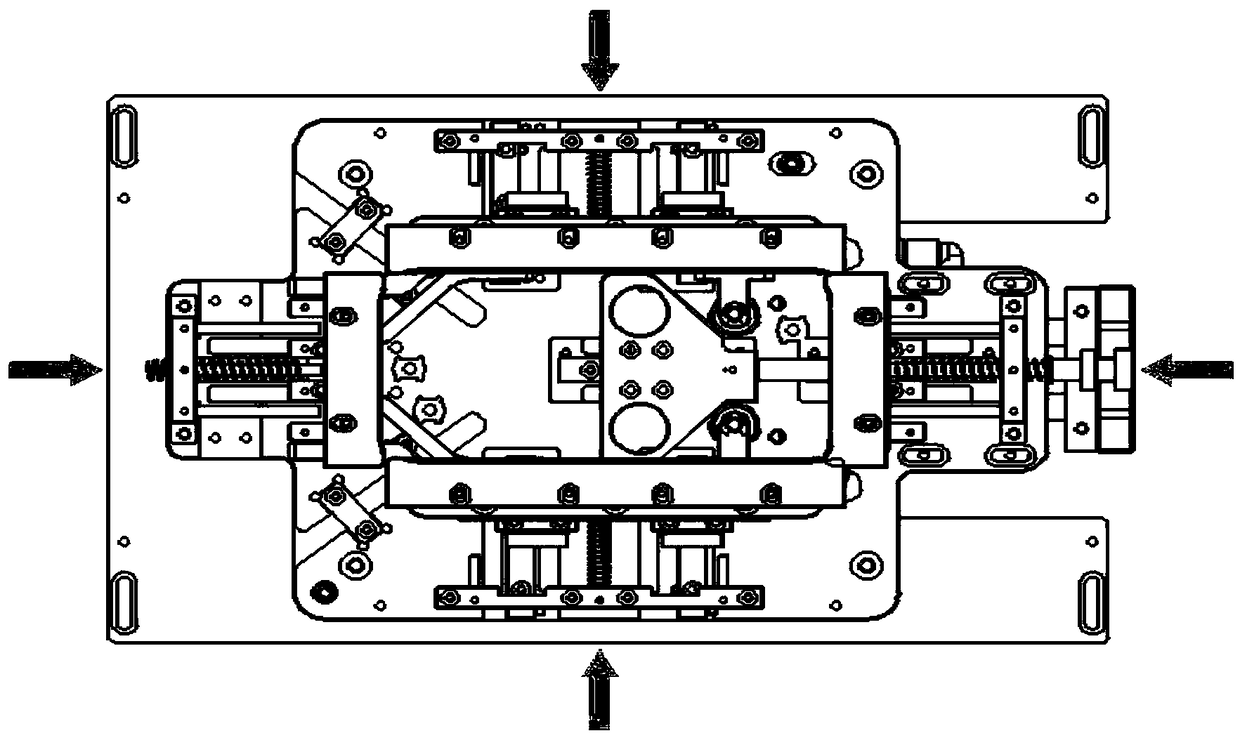
[0020] The present invention provides the clamping mechanism around here through improvement, such as Figure 1-Figure 2 As shown, it can be implemented in the following manner; including the mold base 20 and the driving mechanism 1, the driving mechanism 1 is horizontally arranged on the top edge of the mold base 20, and is fixedly connected with the mold base 20 by screws, and the bottom of the driving mechanism 1 is provided There is a sl...


PUM


Abstract

The invention discloses a peripheral clamping mechanism and an operation method. The peripheral clamping mechanism comprises a die holder and a driving mechanism, wherein the driving mechanism is horizontally arranged at the top edge position of the die holder and is fixedly connected to the die holder through a screw; a sliding block A is arranged at the bottom of the driving mechanism; the sliding block A is horizontally arranged in the middle of the bottom of the driving mechanism and is fixedly connected to the driving mechanism through the screw; a clamping block A is arranged at the topof the sliding block A; the clamping block A is horizontally arranged in the middle of the top of the sliding block A and is fixedly connected to the sliding block A through the screw; a transmissionblock is arranged on one side of the clamping block A; the transmission block is horizontally arranged at one end of the driving mechanism and is fixedly connected to the driving mechanism through thescrew; a sliding block B and a sliding block C which are parallel to each other are arranged at the top of the die holder; and the sliding block B and the sliding block C are horizontally arranged atthe top edge position of the die holder and are fixedly connected to the die holder through the screws. The peripheral clamping mechanism has the advantages of simple operation control, identical peripheral clamping force and consistent running speed of the clamping blocks.

Description

technical field [0001] The invention relates to the technical field of clamping mechanisms, in particular to a peripheral clamping mechanism and an operation method. Background technique [0002] The clamping mechanism is a product used in instrument processing, which plays a role in fixing the components that need to be processed precisely, so as to improve the processing accuracy. [0003] After searching, it is found that the invention of patent No. CN106737793A discloses a "clamping mechanism", which includes jaws, and the jaws are composed of a master arm and a slave arm arranged oppositely; the master arm and the slave arm both include a clamping part and a transmission and are pivotally connected to the base through their respective transmission parts; the transmission parts are at least partly arc-shaped, and the arc-shaped part of the transmission part of the master arm is provided with active teeth, and the arc-shaped part of the transmission part of the slave arm ...

Claims


Application Information

Patent Timeline
Patent Type & Authority Applications(China)
IPC IPC(8): B23Q3/06
CPCB23Q3/06
Inventor 吕军辉周雁飞
Owner 上海莘翔自动化科技有限公司
Learn More