
Grinding device for mechanical processing

A technology of mechanical processing and equipment, which is applied in the field of grinding equipment for mechanical processing, and can solve problems such as affecting efficiency, unfavorable grinding work, and easy fatigue of operators

Inactive Publication Date: 2018-12-21
JIAXING TANGDONG AUTO PARTS CO LTD
View PDF6 Cites 9 Cited by
  • Summary
  • Abstract
  • Description
  • Claims
  • Application Information

AI Technical Summary

Problems solved by technology

[0002] Machining refers to the process of changing the shape, size or performance of a workpiece through a mechanical device. According to the difference in processing methods, it can be divided into cutting processing and pressure processing. It is necessary to process the machine during machining. The product is polished, but the existing grinding equipment requires manual hand-held operation. The vibration generated during grinding will make the operator easy to fatigue, seriously affect the safety of the human body, and also affect the efficiency of production, and the existing grinding equipment does not It has the function of automatic dust collection, causing debris to splash around during grinding, which affects the environment and is not conducive to the grinding work

Method used


Image

  • Grinding device for mechanical processing
  • Grinding device for mechanical processing
  • Grinding device for mechanical processing

Examples


Embodiment Construction

[0022] The following will clearly and completely describe the technical solutions in the embodiments of the present invention with reference to the accompanying drawings in the embodiments of the present invention. Obviously, the described embodiments are only some, not all, embodiments of the present invention. All other embodiments obtained by persons of ordinary skill in the art based on the embodiments of the present invention belong to the protection scope of the present invention.

[0023] According to an embodiment of the present invention, a grinding device for machining is provided.

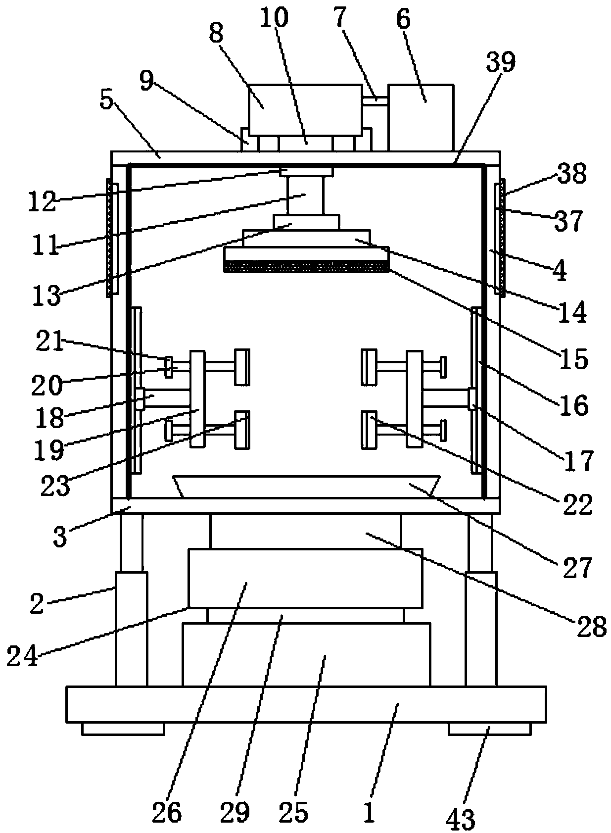
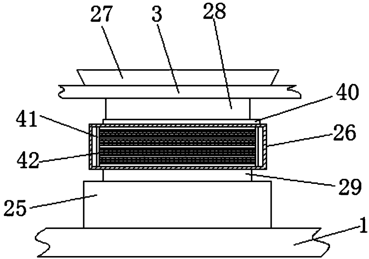
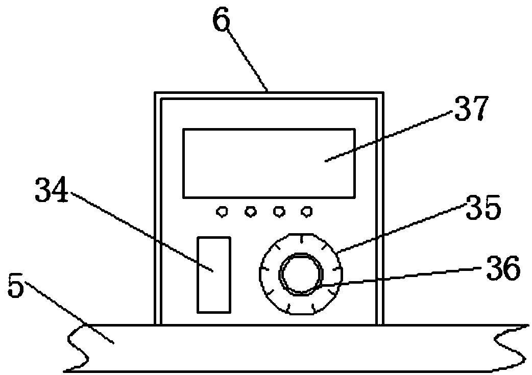
[0024] Such as Figure 1-4 As shown, a grinding equipment for mechanical processing according to an embodiment of the present invention includes a base 1, a support device 2 is symmetrically provided on the top of the base 1, and a support plate 3 is provided on the top of the support device 2, so The top of the support plate 3 is symmetrically provided with a side plate 4, the top of t...


PUM


Abstract

The invention discloses a grinding device for mechanical processing. The grinding device comprises a base. The top of the base is symmetrically arranged with supporting devices. The top of the supporting device is arranged with a supporting plate. The top of the supporting plate is symmetrically arranged with side plates. The top of the side plate is arranged with a top plate. The top of the top plate is arranged with a controller. One side edge of the controller is arranged with a connecting wire, and one end, far away from the controller, of the connecting wire is arranged with a motor. Thebottoms of the supporting plates are both connected with the tops of the top plates. The middle of the bottom end of the motor is arranged with a coupler. The bottom of the coupler is arranged with arotating shaft. The bottom of the rotating shaft penetrates through the top plate and extends below the top plate. The bottom of the top plate is arranged with a fixing ring. The fixing ring is sleeved on the outer side of the rotating shaft. The bottom of the rotating shaft is arranged with a connecting block. The bottom of the connecting block is arranged with a turntable. The bottom of the turntable is arranged with a grinding table.

Description

technical field [0001] The invention relates to the technical field of mechanical processing, in particular to a grinding device for mechanical processing. Background technique [0002] Machining refers to the process of changing the shape, size or performance of a workpiece through a mechanical device. According to the difference in processing methods, it can be divided into cutting processing and pressure processing. It is necessary to process the machine during machining. The product is polished, but the existing grinding equipment requires manual hand-held operation. The vibration generated during grinding will make the operator easy to fatigue, seriously affect the safety of the human body, and also affect the efficiency of production, and the existing grinding equipment does not It has the function of automatic dust collection, which causes debris to splash around during grinding, which affects the environment and is not conducive to the grinding work. [0003] Aiming...

Claims


Application Information

Patent Timeline
Patent Type & Authority Applications(China)
IPC IPC(8): B24B19/00B24B41/06B24B47/12B24B55/06
CPCB24B19/00B24B41/06B24B47/12B24B55/06
Inventor 熊仁兵孙凯杰谭文军
Owner JIAXING TANGDONG AUTO PARTS CO LTD
Learn More