Bicycle with pedal

A bicycle and pedal technology, applied in vehicle parts, rider drive, transportation and packaging, etc., can solve the problems of uncoordinated pedaling, low force conversion efficiency, unreasonable pedal bicycle structure, etc., and achieve reasonable structure and force conversion. Efficient effect

Pending Publication Date: 2018-12-21
许瑞雪 +1
View PDF0 Cites 0 Cited by
  • Summary
  • Abstract
  • Description
  • Claims
  • Application Information

AI Technical Summary

Problems solved by technology

[0004] The purpose of the present invention is to provide a pedal bicycle to solve the problems of unrea

Method used


Image

  • Bicycle with pedal

Examples


Embodiment Construction

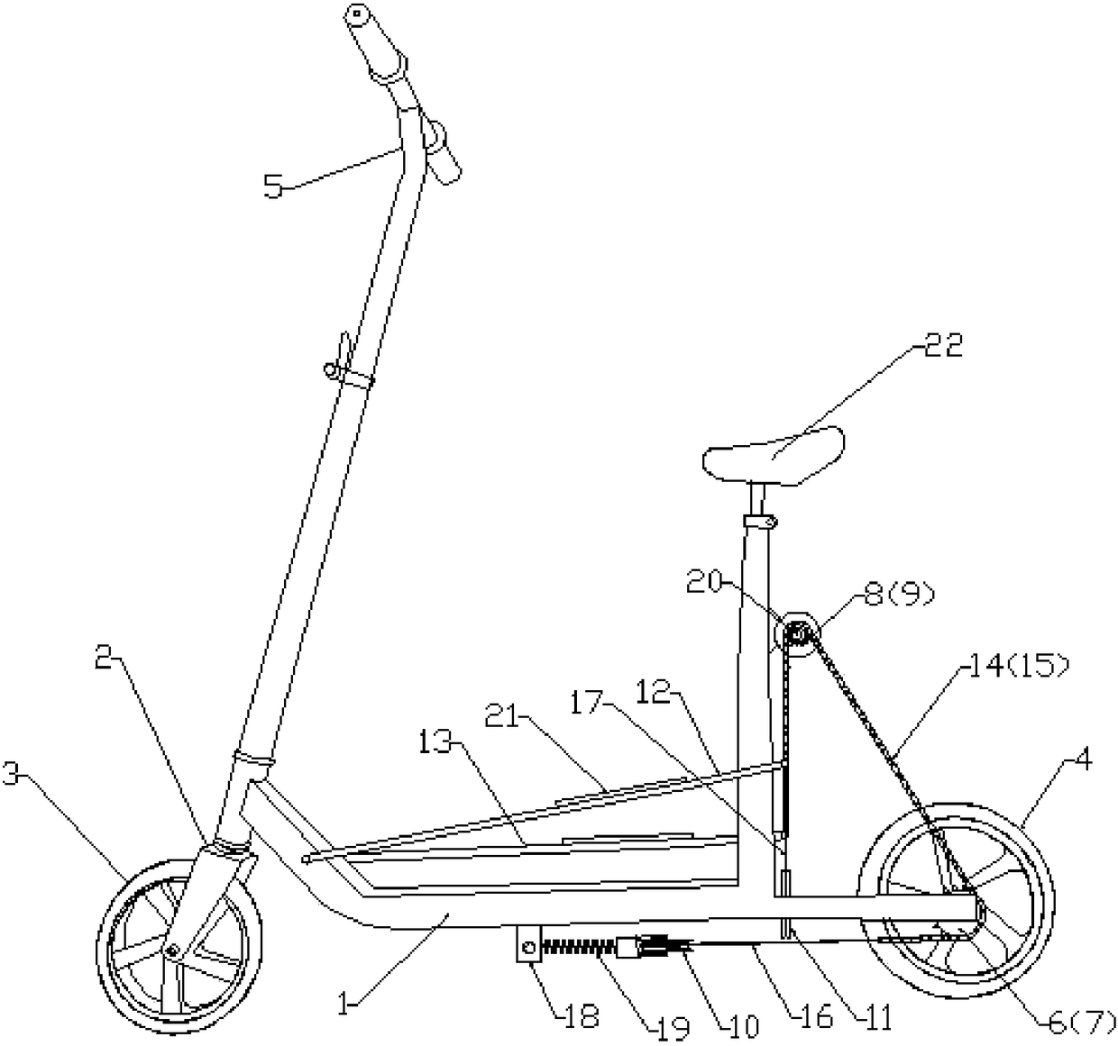
[0019] like figure 1 As shown, a specific embodiment of a pedal bicycle includes a vehicle frame 1, a front fork 2, a front wheel 3, a rear wheel 4 and a handlebar 5, and the front fork 2 is installed on the front side of the vehicle frame 1, and the The handlebar 5 is installed on the upper end of the front fork 2, the front wheel 3 is installed on the lower end of the front fork 2, the steering of the front wheel is controlled by the handlebar, and the rear wheel 4 is installed on the rear side of the vehicle frame 1 to form a whole moving device, which is the same as the prior art.

[0020] What is unique in this specific embodiment is that the left and right sides of the rear wheel 4 are respectively equipped with a first flywheel 6 and a second flywheel 7 ( figure 1 not shown), the first flywheel and the second flywheel drive the rear wheel to rotate forward when rotating forward, and the first flywheel and the second flywheel will not produce force on the rear wheel whe...


PUM


Abstract

The invention discloses a pedal bicycle, comprising a frame, a front fork, a front wheel, a rear wheel and a handlebar. The left and right sides of the rear wheel are respectively provided with a first flywheel and a second flywheel, the first sprocket and the second sprocket are rotatably arranged on the frame, and the first runner is horizontally arranged below the frame. A first pedal and a second pedal are hinged on the front side of the frame, one end of the first chain is connected to the upper side of the rear end of the first pedal, and the first chain bypasses the first sprocket and the first flywheel; One end of the second chain is connected to the upper side of the rear end of the second pedal, and the second chain passes around the second sprocket and the second flywheel; The first runner is wound with a first drawing wire, and both ends of the first drawing wire are fixedly connected with the other end of the first chain and the other end of the second chain respectively.The structure of the invention is more reasonable, each step of the first pedal or the second pedal is converted into the power for the rear wheel to advance, the force conversion efficiency is high,and the first pedal and the second pedal move up and down with linkage, and the first pedal and the second pedal are more coordinated.

Description

technical field [0001] The invention relates to the field of bicycles, in particular to a pedal bicycle. Background technique [0002] There are following deficiencies in the existing bicycle transmission: one is that the torque conversion efficiency is not high. When the existing bicycle is riding, when the crank is in a horizontal state, the power of the person stepping on the pedals can make the crankshaft output the maximum torque; The maximum value when the crank is in the vertical state; when the crank is in the vertical state, the force direction of the person stepping on the pedal overlaps with the center of the central axis. At this time, the crankshaft has no torque output when the pedal is stepped on hard. Therefore, the existing transmission device cannot adjust the vertical direction The maximum pedaling force is converted into rotational torque. The second is insufficient driving force. Existing bicycles are ridden in a sitting position. The bicycle seat bea...

Claims


Application Information

Patent Timeline
IPC IPC(8): B62M1/28
CPCB62M1/28
Inventor 许瑞雪许瑞超
Owner 许瑞雪
Why Eureka
Try Eureka