
Strip-shaped material veering and conveying device

A conveying device and material technology, which is applied in the field of strip-shaped material steering conveying device, can solve the problems of difficult maintenance, unstable operation of equipment, increased cost, etc., and achieve the effects of convenient maintenance, low use cost and simple transmission structure

Active Publication Date: 2018-12-21
胡刘满
View PDF7 Cites 3 Cited by
  • Summary
  • Abstract
  • Description
  • Claims
  • Application Information

AI Technical Summary

Problems solved by technology

[0002] In the field of mechanical processing, it is often necessary to convey rod-shaped or strip-shaped materials, and the conveying direction of materials is required to be freely adjustable under certain special processing conditions, such as pipe bending and forming equipment, cable feeding mechanisms, etc. Higher requirements are put forward for the material conveying device. To solve this technical problem, the traditional conveying equipment generally adopts the method of installing the conveying roller on the turntable, and then adding an additional power mechanism on the turntable. The disadvantage is that the additional power mechanism will not only increase the cost, but also easily lead to unstable operation of the equipment, difficult maintenance, and poor reliability of the equipment

Method used


Image

  • Strip-shaped material veering and conveying device
  • Strip-shaped material veering and conveying device
  • Strip-shaped material veering and conveying device

Examples


Embodiment Construction

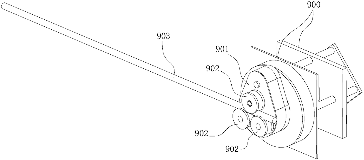
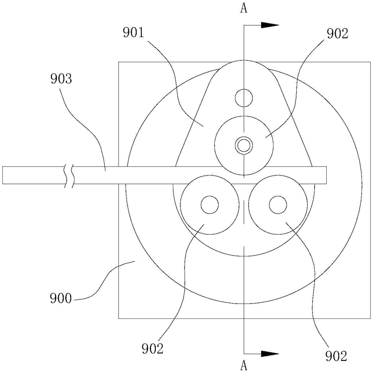
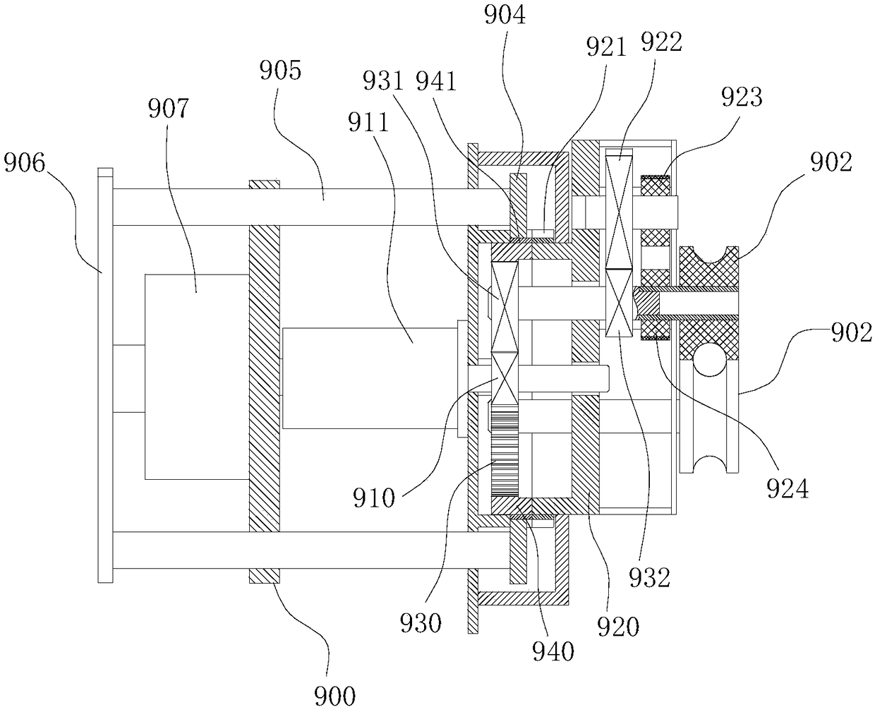
[0015] combine Figure 1 to Figure 5 , the present invention is further described:

[0016] In order to make the objects and advantages of the present invention clearer, the present invention will be described in detail below in conjunction with the examples. It should be understood that the following words are only used to describe one or several specific implementation modes of the present invention, and do not strictly limit the protection scope of the specific claims of the present invention.

[0017] Such as Figures 1 to 5 As shown, a strip-shaped material turning conveying device includes at least three conveying rollers 902, each conveying roller 902 is arranged alternately on both sides of the strip-shaped material 903, and the rotation direction of the conveying rollers 902 on both sides of the strip-shaped material 903 is opposite , and the roller surface of each conveying roller 902 is provided with an annular groove for accommodating the strip-shaped material 90...


PUM


Abstract

The invention belongs to the technical field of material conveying equipment, in particular to a strip-shaped material veering and conveying device capable of freely changing the strip-shaped materialconveying direction. The device comprises at least three conveying rollers, the conveying rollers are arranged on the two sides of the strip-shaped material in a staggered mode, and the rotating directions of the conveying rollers on the two sides of the strip-shaped material are opposite; a roller surface of each conveying roller is provided with an annular groove used for containing strip-shaped material; all conveying rollers are arranged on the same rotating disc in a rotating mode, and the rotating disc is rotationally arranged on a machine frame; and the rotating disc and the conveyingrollers are driven by the same driving component, and a power switching mechanism is arranged between the driving component and the rotating disc and the conveying rollers. According to the device, the revolution and rotation of a planetary gear mechanism are ingeniously utilized to realize the conveying and veering of the strip-shaped material, and the transmission structure is simple and reliable; and the device only needs one set of motor to drive, the use cost is low, and the maintenance is convenient.

Description

technical field [0001] The invention belongs to the technical field of material conveying equipment, and in particular relates to a strip-shaped material turning and conveying device capable of freely changing the conveying direction of the strip-shaped material. Background technique [0002] In the field of mechanical processing, it is often necessary to convey rod-shaped or strip-shaped materials, and the conveying direction of materials is required to be freely adjustable under certain special processing conditions, such as pipe bending and forming equipment, cable feeding mechanisms, etc. Higher requirements are put forward for the material conveying device. To solve this technical problem, the traditional conveying equipment generally adopts the method of installing the conveying roller on the turntable, and then adding an additional power mechanism on the turntable. The disadvantage is that the additional power mechanism will not only increase the cost, but also easily...

Claims


Application Information

Patent Timeline
Patent Type & Authority Applications(China)
IPC IPC(8): B65G47/74
CPCB65G47/74
Inventor 李翠平
Owner 胡刘满
Learn More