
Universal liquid filling valve

A filling valve, all-purpose technology, used in liquid bottling, liquid processing, packaging, etc., can solve the problems of incompatibility, different designs, adding guide posts and sliders, etc., to achieve the effect of good airtightness and compact structure

Inactive Publication Date: 2018-12-21
ZHANGJIAGANG WANJIN MACHINERY CO LTD
View PDF7 Cites 0 Cited by
  • Summary
  • Abstract
  • Description
  • Claims
  • Application Information

AI Technical Summary

Problems solved by technology

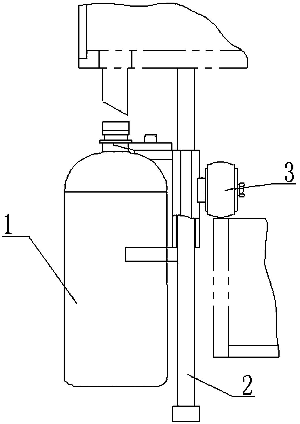
[0002] The filling machine is a machine for filling objects. With the development of the beverage industry, the filling machinery has developed rapidly, and the filling speed is fast and the degree of automation is high. During the filling work, the filling valve is generally facing downward, and the bottle body The mouth of the bottle is super-upper, and the two are sealed and combined, so that the bottle body and the filling liquid are at equal pressure, and then the filling bottle body is filled. The existing bottle body generally adopts a cam structure, and the bottle body is conveyed by the rotation of the cam. , during filling, due to the rotation of the bottle body, there is a certain gap between the bottle mouth and the valve mouth. The traditional solution is generally to set a lifting device on the cam, such as figure 1 As shown, after the bottle mouth and the filling valve are kept stable, the bottle is filled, and then the bottle body is transferred after the filling is completed. This method is currently commonly used, but this method brings requirements to the cam design and increases the guide Columns and sliders increase the complexity of the design. Different glass bottles and plastic bottles are designed differently and cannot be used universally. Therefore, the present invention provides a liquid universal filling valve, which can be replaced by a liquid universal filling valve. Cam guide post, and the present invention is based on the improvement of the traditional valve, the required hardware is reduced, the burden on the enterprise is reduced, and the sealed filling of different bottle structures can also be completed

Method used


Image

  • Universal liquid filling valve
  • Universal liquid filling valve

Examples


Embodiment Construction

[0016] The preferred embodiments of the present invention will be described in detail below in conjunction with the accompanying drawings, so that the advantages and features of the present invention can be more easily understood by those skilled in the art, so as to define the protection scope of the present invention more clearly.

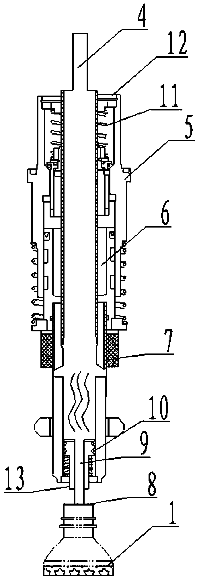
[0017] see figure 1 with figure 2 , the embodiment of the present invention includes:

[0018] The liquid universal filling valve includes four components: a valve body, an air return pipe, a sleeve and a moving pipe, wherein the valve body, the air return pipe, the sleeve and the moving pipe are all made of 304 alloy steel, Wherein the valve body is located at the upper end, the casing is arranged at the lower end of the valve body, the air return pipe is arranged in the middle cavity between the valve body and the casing pipe, the moving pipe is arranged in the inner cavity of the casing pipe, and a valve nozzle is arranged at the lower end o...


PUM


Abstract

The invention discloses a universal liquid filling valve. The valve comprises four constituent portions including a valve body, an air return pipe, a sleeve and a moving pipe which are all made of a 304 alloy steel material. The valve body is located at the upper end. The sleeve is located at the lower end of the valve body. The air return pipe is arranged in a middle cavity formed between the valve body and the sleeve. The moving pipe is arranged in an inner cavity of the sleeve, and a valve mouth is formed in the lower end of the valve body. The universal liquid filling valve provided by theinvention is compact in structure, the moving pipe can move up and down under water pressure, better sealing between a bottle and the valve is achieved, and the universal liquid filling valve can adapt to filling operation on various bottles.

Description

technical field [0001] The invention relates to the technical field of filling machinery and equipment, in particular to a liquid universal filling valve. Background technique [0002] The filling machine is a machine for filling objects. With the development of the beverage industry, the filling machinery has developed rapidly, and the filling speed is fast and the degree of automation is high. During the filling work, the filling valve is generally facing downward, and the bottle body The mouth of the bottle is super-upper, and the two are sealed and combined, so that the bottle body and the filling liquid are at equal pressure, and then the filling bottle body is filled. The existing bottle body generally adopts a cam structure, and the bottle body is conveyed by the rotation of the cam. , during filling, due to the rotation of the bottle body, there is a certain gap between the bottle mouth and the valve mouth. The traditional solution is generally to set a lifting devic...

Claims


Application Information

Patent Timeline
IPC IPC(8): B67C3/26B67C3/28
CPCB67C3/2637B67C3/28
Inventor 秦志洪
Owner ZHANGJIAGANG WANJIN MACHINERY CO LTD
Learn More