A bridge anti-collision guardrail and a construction method thereof

A technology for anti-collision guardrails and bridges, used in bridges, bridge parts, bridge construction, etc., can solve the problems of turning out of the bridge, difficult maintenance, and high cost, improving structural stability, consuming impact energy, and reducing installation errors. Effect

Inactive Publication Date: 2018-12-21
ZHEJIANG COLLEGE OF CONSTR
View PDF0 Cites 14 Cited by
  • Summary
  • Abstract
  • Description
  • Claims
  • Application Information

AI Technical Summary

Problems solved by technology

There are certain defects in this structure: when the vehicle hits the anti-collision barrier in an unexpected situation, because it is a rigid collision, these barriers cannot absorb the collision kinetic energy of the car. The reversal deviates from the original lane, and a second collision with a car driving at high speed occurs, causing multiple car crashes and deaths, and even directly turning over the bridge, aggravating the hazards of the accident, poor safety protection performance, and more collisions After that, the concrete of the anti-collision guardrail will also peel off, and the steel bars will be exposed, which will affect the appearance, and it is very unsafe and inconvenient to maintain. Moreover, the construction period of this type of reinforced concrete anti-collision guardrail is long, time-consuming, laborious, low in construction efficiency, and high in cost. Difficult to maintain

Method used


Image

  • A bridge anti-collision guardrail and a construction method thereof
  • A bridge anti-collision guardrail and a construction method thereof
  • A bridge anti-collision guardrail and a construction method thereof

Examples


Embodiment Construction

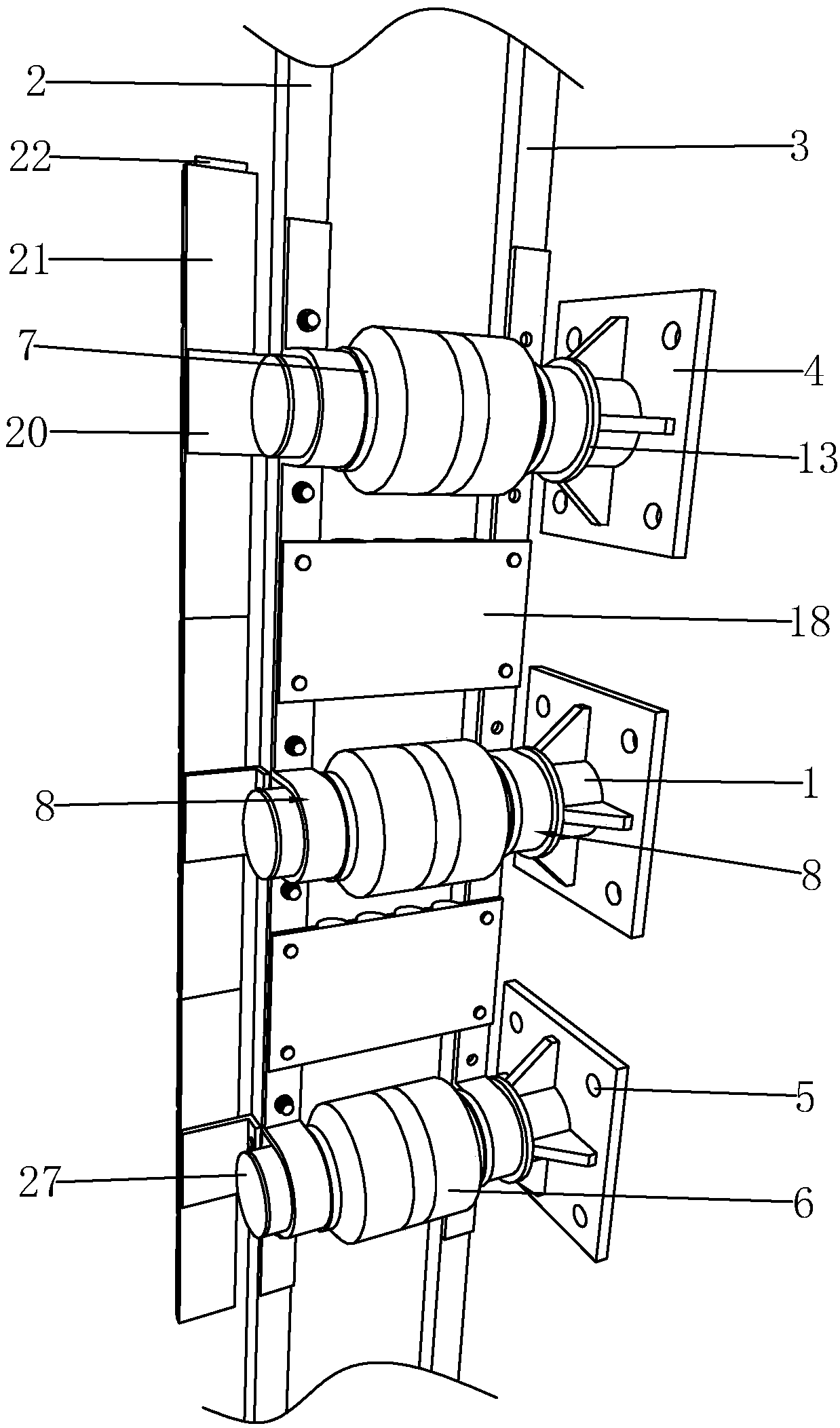
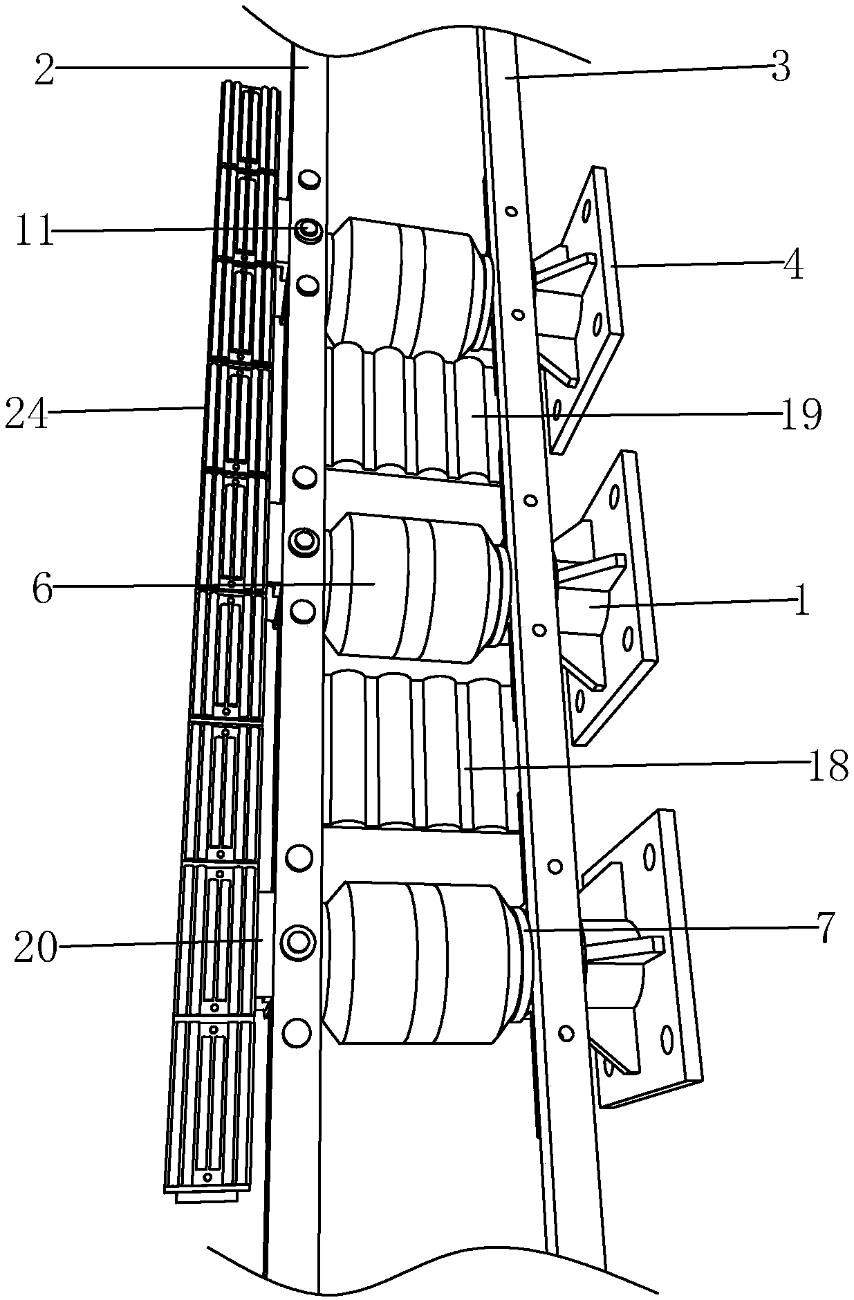
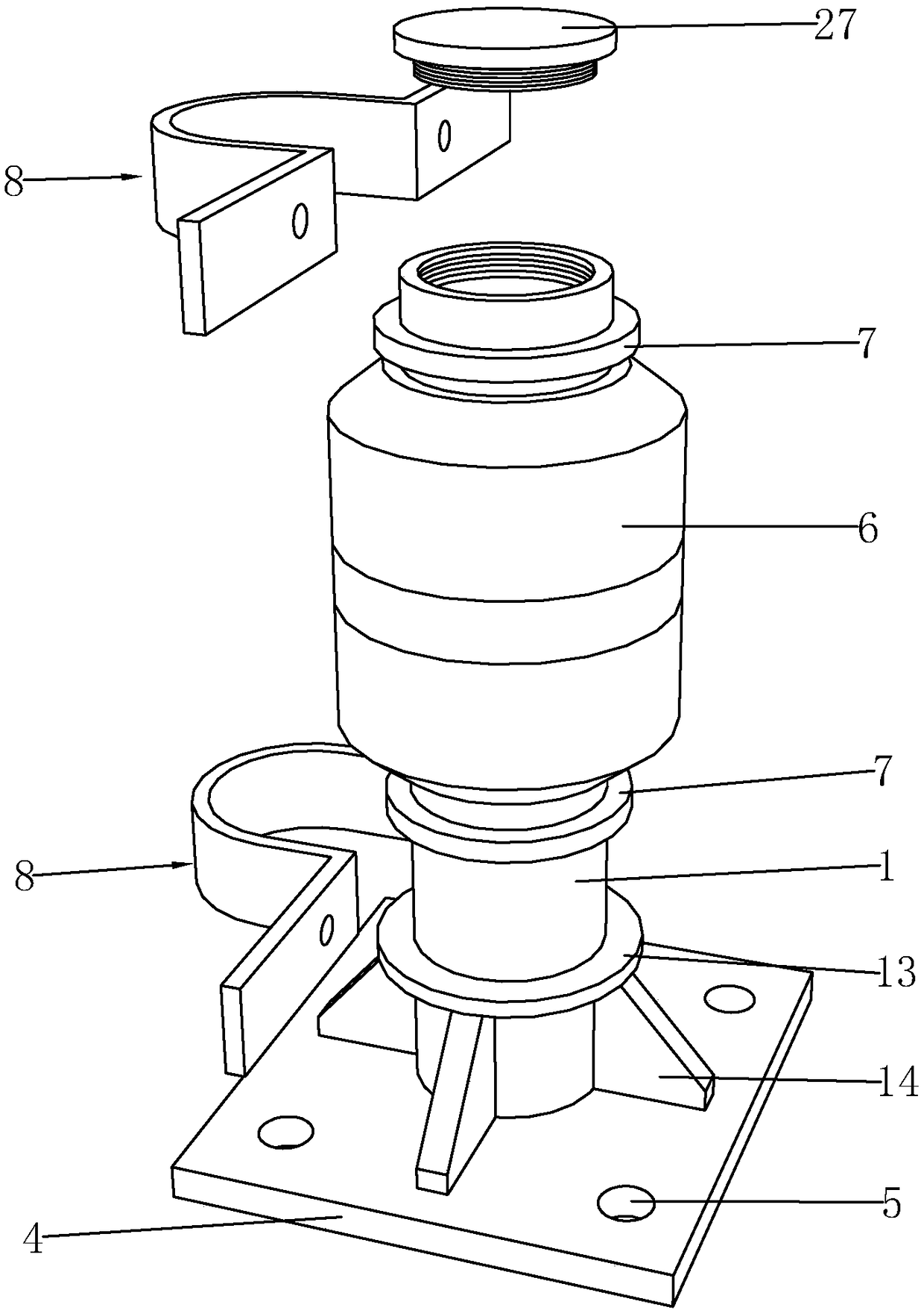
[0035] like Figure 1 to Figure 6 Shown, be a kind of bridge anti-collision guardrail of the present invention, comprise column 1, upper railing 2 and lower railing 3, column 1 is located between upper railing 2 and lower railing 3, the bottom of column 1 is provided with support plate 4, supports An anchor hole 5 is provided on the plate 4, and ground nails are driven into the anchor hole 5 to realize the fixing of the column 1 on the bridge surface, which is easy to disassemble and convenient for maintenance. The column 1 is respectively sleeved with a buffer cylinder 6 and a convolving ring 7. The buffer cylinder 6 is located between the limit seats 8, and the convolute ring 7 is located between the buffer cylinder 6 and the limit seat 8. The convoluted circles 7 arranged up and down are convenient for the buffer cylinder. 6 Rotate smoothly when being hit, both ends of the column 1 are fixed on the upper railing 2 and the lower railing 3 through the limit seat 8, the limit ...


PUM


Abstract

The invention discloses a bridge anti-collision guardrail and a construction method thereof, Collision barriers include columns, An upper rail and a low rail are respectively sleeved with a buff cylinder and a swirling ring on that upright column, the two ends of the upright column are fix on the upper rail through a limiting seat, the lower rail is provided with a fixing ring on the upright column, the fixing ring is in contact with the limiting seat located below, an L-shaped mounting plate is provided on the upper rail, an L-shaped mounting plate is provided with an anti-collision plate, and a cushioning guardrail plate is provided on the anti-collision plate; The construction method comprises the following steps: (a) route marking; (b) Post positioning; (c) Installation of lower railings; (d) installation of an upper railing; (e) Installation of cushion shields; (f) Installation of bumper plates; (g) Installation of remaining uprights. The anti-collision guardrail of the inventionhas the advantages of high stability, convenient installation, cushioning and anti-collision, high safety, easy operation, orderly and reasonable construction, fast and convenient construction, time and labor saving, low construction intensity and convenient maintenance in the later period. The invention has the advantages of high stability, convenient installation, cushioning and anti-collision,high safety, easy operation, orderly and reasonable construction method, fast and convenient construction, and low construction intensity.

Description

technical field [0001] The invention belongs to the field of traffic safety facilities, in particular to a bridge anti-collision guardrail and a construction method thereof. Background technique [0002] At present, a large number of viaducts are built in cities. In order to prevent vehicles from falling over the bridges, reinforced concrete anti-collision guardrail facilities are usually used. There are certain defects in this structure: when the vehicle hits the anti-collision barrier in an unexpected situation, because it is a rigid collision, these barriers cannot absorb the collision kinetic energy of the car. The reversal deviates from the original lane, and a second collision with a car driving at high speed occurs, causing multiple car crashes and deaths, and even directly turning over the bridge, aggravating the hazards of the accident, poor safety protection performance, and more collisions After that, the concrete of the anti-collision guardrail will also peel of...

Claims


Application Information

Patent Timeline
Patent Type & Authority Applications(China)
IPC IPC(8): E01D19/10E01D21/00
CPCE01D19/103E01D21/00
Inventor 刘俊龙
Owner ZHEJIANG COLLEGE OF CONSTR
Why Eureka
Try Eureka