Liquid-controlled type under-shaft savaging tool

A salvage tool and hydraulic control technology, applied in wellbore/well parts, earthwork drilling and other directions, can solve the problems of falling fish, poor control of the rotation angle, and failure of salvage, etc., and achieve the effect of preventing falling fish from falling.

Active Publication Date: 2018-12-21
SOUTHWEST PETROLEUM UNIV
View PDF6 Cites 5 Cited by
  • Summary
  • Abstract
  • Description
  • Claims
  • Application Information

AI Technical Summary

Problems solved by technology

However, these two methods have their disadvantages: it is difficult to operate the fishing tool in a horizontal well by rotating the drill string, and it is not easy to rotate the drill string, and the rotation angle is not easy to control; the fishing tool is completed by lifting the drill string up and down. Exit, if stuck during the fishing process, you need to lift and lower the drill string to release the stuck, it can not be realized well, it is easy to cause the fish to fall off, and the fishing fails

Method used


Image

  • Liquid-controlled type under-shaft savaging tool
  • Liquid-controlled type under-shaft savaging tool
  • Liquid-controlled type under-shaft savaging tool

Examples


Embodiment example 1

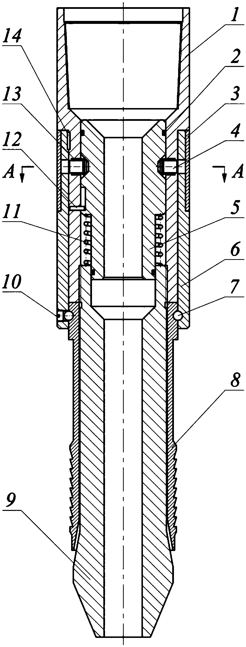
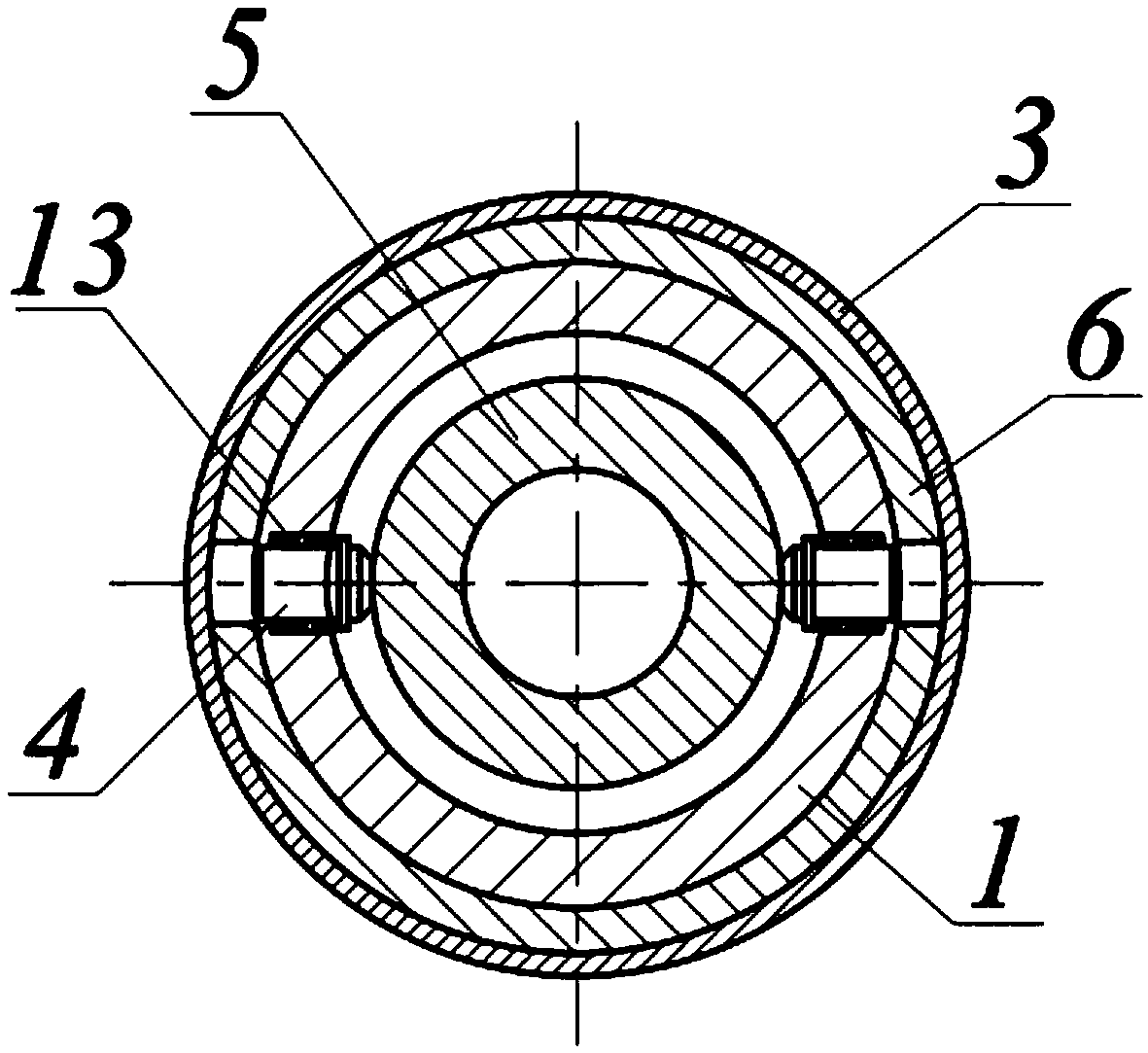
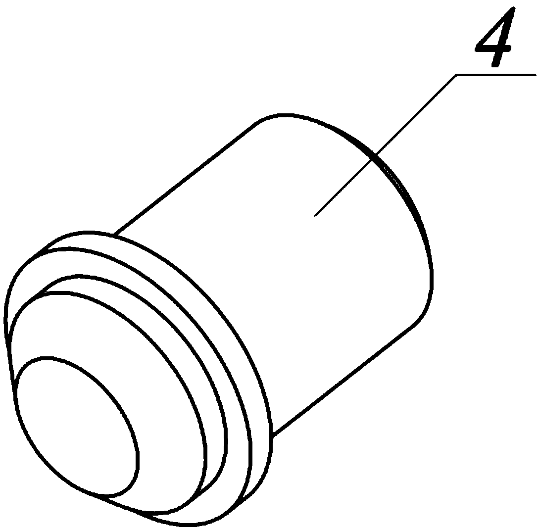
[0018] Such as Figure 1-Figure 7 As shown, a hydraulically controlled downhole fishing tool is mainly composed of a joint 1, a sealing ring 2, a sliding sleeve 3, a fixed pin 4, a piston 5, a casing 6, a steel ball 7, slips 8, a mandrel 9, a screw 10, a reset Spring 11, travel pin 12, pin spring 13, semicircular key 14 are characterized in that: described joint 1 and mandrel 9 are connected by screw thread, and joint 1 is provided with the pin hole that installs fixed pin 4 and pin spring 13; The piston 5 is installed in the joint 1, and its upper end is provided with an annular groove 5a that matches the fixed pin 4, and both sides of the annular groove are provided with inclined surfaces, and the middle part of the piston 5 is provided with a stroke groove 5b, which is used to control the stroke of the piston 5 The fixed pin 4 is installed in the pin hole of the joint 1, and its other end is inserted into the ring groove 5a of the piston 5; the shell 6 is set on the joint 1...

Embodiment example 2

[0020] During the fishing operation, the fishing tool is connected to the lowermost part of the downhole string, the threads are tightened, and the tool is lowered into the well. When the lowering device is 1-2m away from the top of the fish, stop lowering and record the total weight suspended at this time. Then turn on the mud pump to rinse the fish. After washing the fish, turn off the mud pump and continue to lower the fishing tool slowly. When the suspended weight returns to lower, stop lowering and try to lift the drill string. After confirming that the fish is caught, lift the device and take out the fish. If the fish gets stuck in fishing, lower the tool string, stop the lowering when the index weight gauge is lowered below the suspended weight, turn on the mud pump for about 10 seconds, and then lift the string to pull the tool out of the fish.


PUM


Abstract

The invention discloses a liquid-controlled type under-shaft savaging tool. The tool is composed of a joint, a sealing ring, a sliding sleeve, a fixing pin, a piston, a housing, a steel bead, a slip,a mandrel, a screw, a restoring spring, a stroke pin, a pin spring and a semi-circular button and is characterized in that the salvaging tool is connected with the lowermost part of an under-shaft piping, and threads are tightly screwed to lower the tool into a shaft. Lowering is stopped when a lowering device is 1-2 m from the top of fish, and the total suspension weight is recorded. A sludge pump is started to flush the fish, the sludge pump is switched off after the fish is washed clean, and the salvaging tool is slowly lowered again. When the suspension weight is reduced, lowering is stopped to try to lift a drilling column, when it is confirmed that the fish is caught, and the salvaging tool is lifted upwards to take out the fish. If fish salvaging is blocked, tool piping is lowered,lowering is stopped when a weight indicator is lowered than the suspension weight again, the sludge pump is started for around 10 seconds, the piping is lifted upwards, and the tool is taken out fromthe fish.

Description

technical field [0001] The invention relates to a fishing tool, in particular to a hydraulic-controlled downhole fishing tool, which belongs to the technical field of petroleum engineering or mechanical engineering. Background technique [0002] At present, the exploitation of many oil and gas wells in my country has entered the middle and later stages, the well depth is large and the downhole environment is complex, and downhole accidents are increasing year by year, the most prominent of which is the drop of downhole tools or pipe strings. If it is not dealt with in time, it will not only delay the construction period, but also cause the scrapping of oil and gas wells in severe cases, resulting in huge economic losses. The most common way to deal with downhole tool or pipe string drop is to use fishing tools to carry out fishing operations. [0003] Most of the fishing tools used in China are slip-returnable fishing tools, which bite the fish through the multi-lobe slips ...

Claims


Application Information

Patent Timeline
Patent Type & Authority Applications(China)
IPC IPC(8): E21B31/18
CPCE21B31/18
Inventor 汤历平王成涛祝效华
Owner SOUTHWEST PETROLEUM UNIV
Why Eureka
Try Eureka