Ball-type valve assembly structure

An assembly structure and ball-type technology, which is applied to variable displacement pump components, components of pumping devices for elastic fluids, machines/engines, etc., can solve the problem of laborious disassembly and assembly, narrow internal space of the liquid end, increased Cost and labor load of operators and other issues, to achieve the effect of avoiding sticking, convenient disassembly and improving work efficiency

Pending Publication Date: 2018-12-21
YANTAI JEREH PETROLEUM EQUIP & TECH CO LTD
View PDF5 Cites 110 Cited by
  • Summary
  • Abstract
  • Description
  • Claims
  • Application Information

AI Technical Summary

Problems solved by technology

However, this type of spherical ball cage and the ball seat are connected by threads. During the actual operation, the sand particles in the sand-carrying liquid can easily enter the connecting thread. Therefore, when the pump is regularly dismantled and inspected, the ball cage and In the case of the valve seat, due to ...

Method used


Image

  • Ball-type valve assembly structure
  • Ball-type valve assembly structure
  • Ball-type valve assembly structure

Examples


Embodiment Construction

[0021] The present invention will be further described through the embodiments below in conjunction with the accompanying drawings.

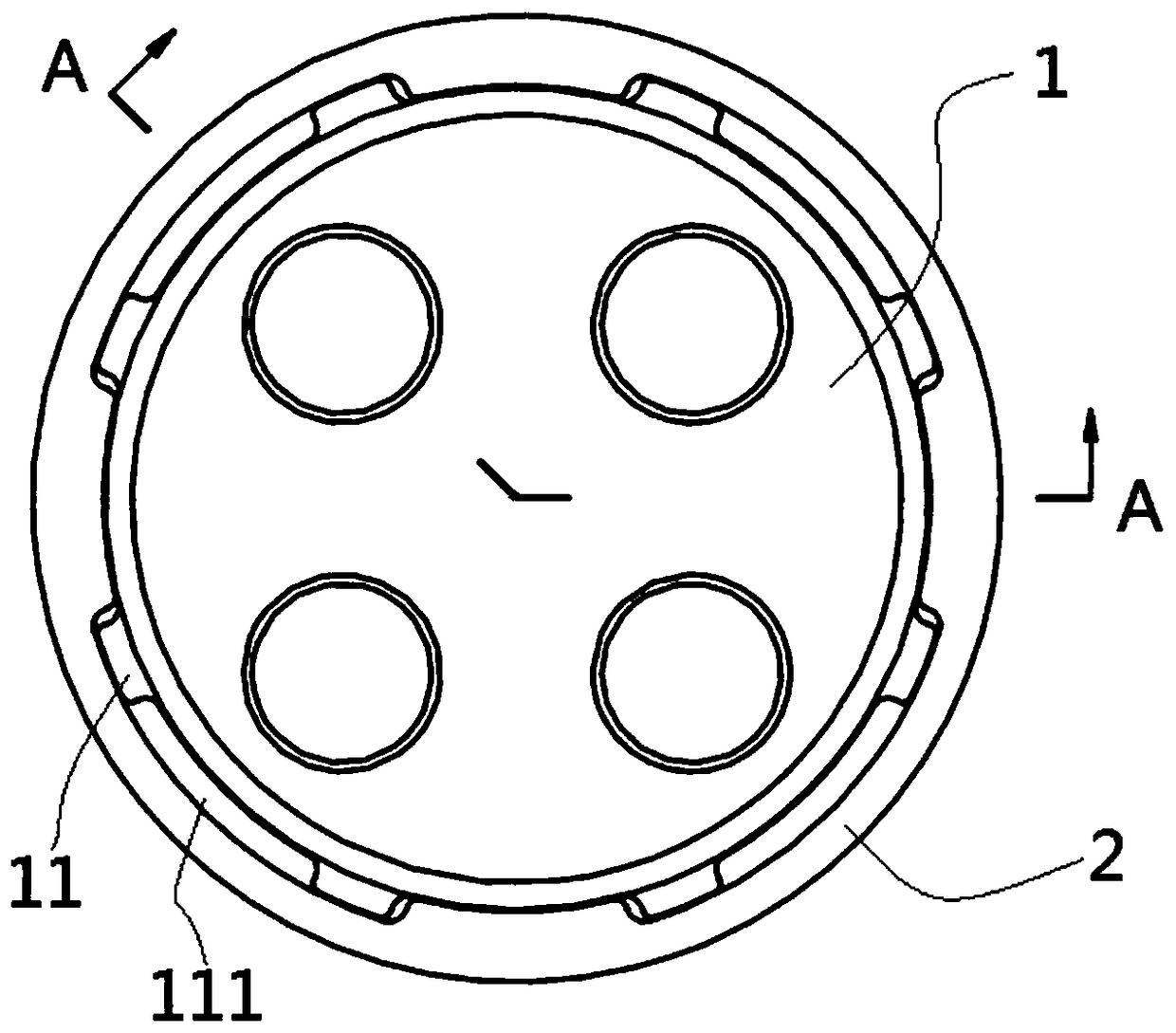
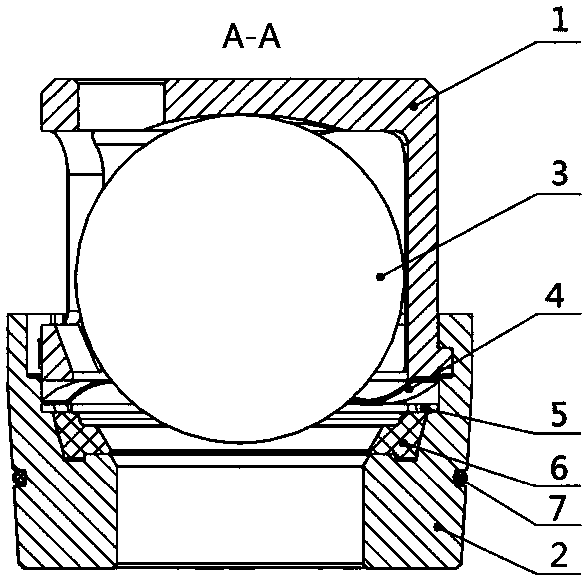
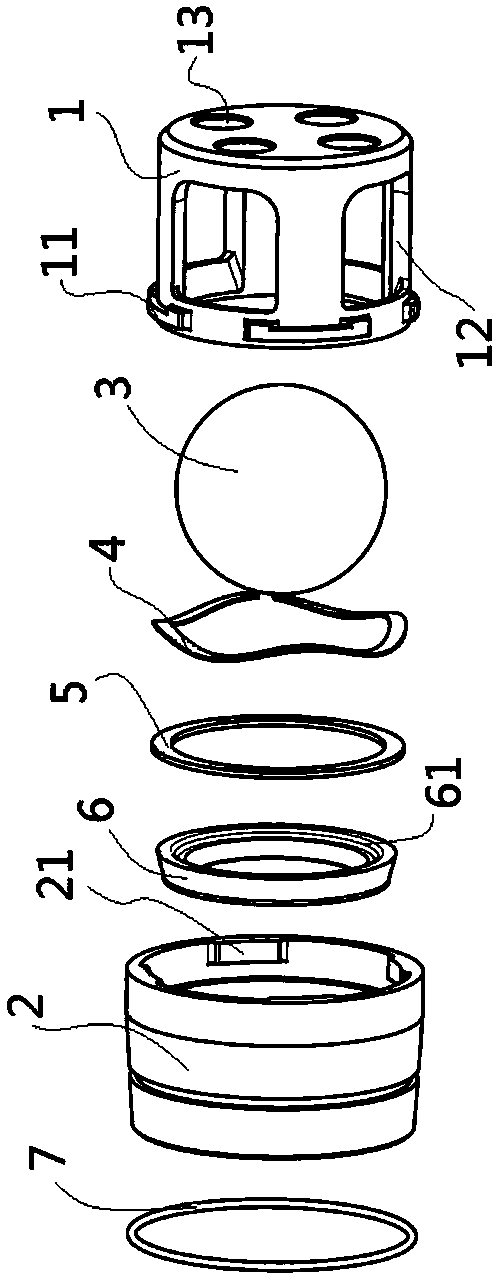
[0022] Such as Figure 1 to Figure 3 As shown, the ball type valve assembly structure of the present invention includes valve seat 2, valve rubber 6, steel ball 3 and ball cage 1, valve rubber 6 is installed on the inner side of valve seat 2, steel ball 3 is installed on The top of the Vall rubber 6 and the outside of the steel ball 3 are provided with a ball cage 1. During operation, when the fluid flows upward from the bottom of the valve seat 2, the steel ball 3 can be lifted up and moved upward, and then the steel ball 3 is separated from the valve rubber 6 and the valve seat 2 to form a gap for the fluid to pass through, and finally from the ball cage 1 The side fluid hole 12 flows out; when the fluid enters the side fluid hole 12 of the ball cage 1 and wants to flow downward, due to the self-weight of the fluid and the steel ball 3 itself...


PUM


Abstract

The invention relates to a ball-type valve assembly structure, and belongs to the technical field of oil-gas exploitation equipment. The ball-type valve assembly structure comprises a valve seat, valve rubber arranged on the inner side of the valve seat, a steel ball positioned above the valve rubber, and a ball cage positioned outside the steel ball, a first clamping piece is arranged on the lower portion of the outer side of the ball cage, a second clamping piece matched with the first clamping piece is arranged on the upper portion of the inner side of the valve seat, and an elastic piece is arranged between the valve seat and the ball cage. The ball-type valve assembly structure has the advantages that the valve seat is connected with the ball cage through a clamping groove structure so that the situations that the clamping stagnation occurs and dismounting is difficult due to sand particle entering can be avoided, and the working efficiency of dismounting and checking a pump can be improved.

Description

technical field [0001] The invention relates to a ball-type valve assembly structure, which belongs to the technical field of oil and gas exploitation equipment, and is especially suitable for oil field fracturing and well cementing plunger pumps. Background technique [0002] The valve assembly is a check valve assembly, which can be used as an important component of the hydraulic end of the plunger pump. It is widely used in oilfield fracturing and cementing plunger pumps. Its function is to As the pressure changes due to the continuous reciprocating movement of the plunger, the valve is continuously opened and closed to realize low-pressure suction and high-pressure discharge of the fluid medium. [0003] The common valve assembly can be divided into two categories, one is composed of valve body, valve spring, valve rubber and valve seat, valve rubber is nested on the valve body, valve rubber and valve When the seat starts to contact, it is surface contact. When the high...

Claims


Application Information

Patent Timeline
IPC IPC(8): F04B53/10F04B53/22
CPCF04B53/1002F04B53/22
Inventor 菅保国崔海萍崔文平郭涛
Owner YANTAI JEREH PETROLEUM EQUIP & TECH CO LTD
Why Eureka
Try Eureka