
Display system and method used for operating display system

一种显示系统、显示器的技术,应用在数字输出到显示设备、静态指示器、阴极射线管指示器等方向,能够解决显示设备设置复杂调整工作等问题,达到节省手动操作、减少设置时间的效果

Active Publication Date: 2018-12-21
QISDA SUZHOU +1
View PDF11 Cites 2 Cited by
  • Summary
  • Abstract
  • Description
  • Claims
  • Application Information

AI Technical Summary

Problems solved by technology

Therefore, the setting of the display device is complicated and requires a lot of adjustment work

Method used


Image

  • Display system and method used for operating display system
  • Display system and method used for operating display system
  • Display system and method used for operating display system

Examples


Embodiment Construction

[0030] In order to have a further understanding of the purpose, structure, features, and functions of the present invention, the following detailed descriptions are provided in conjunction with the embodiments.

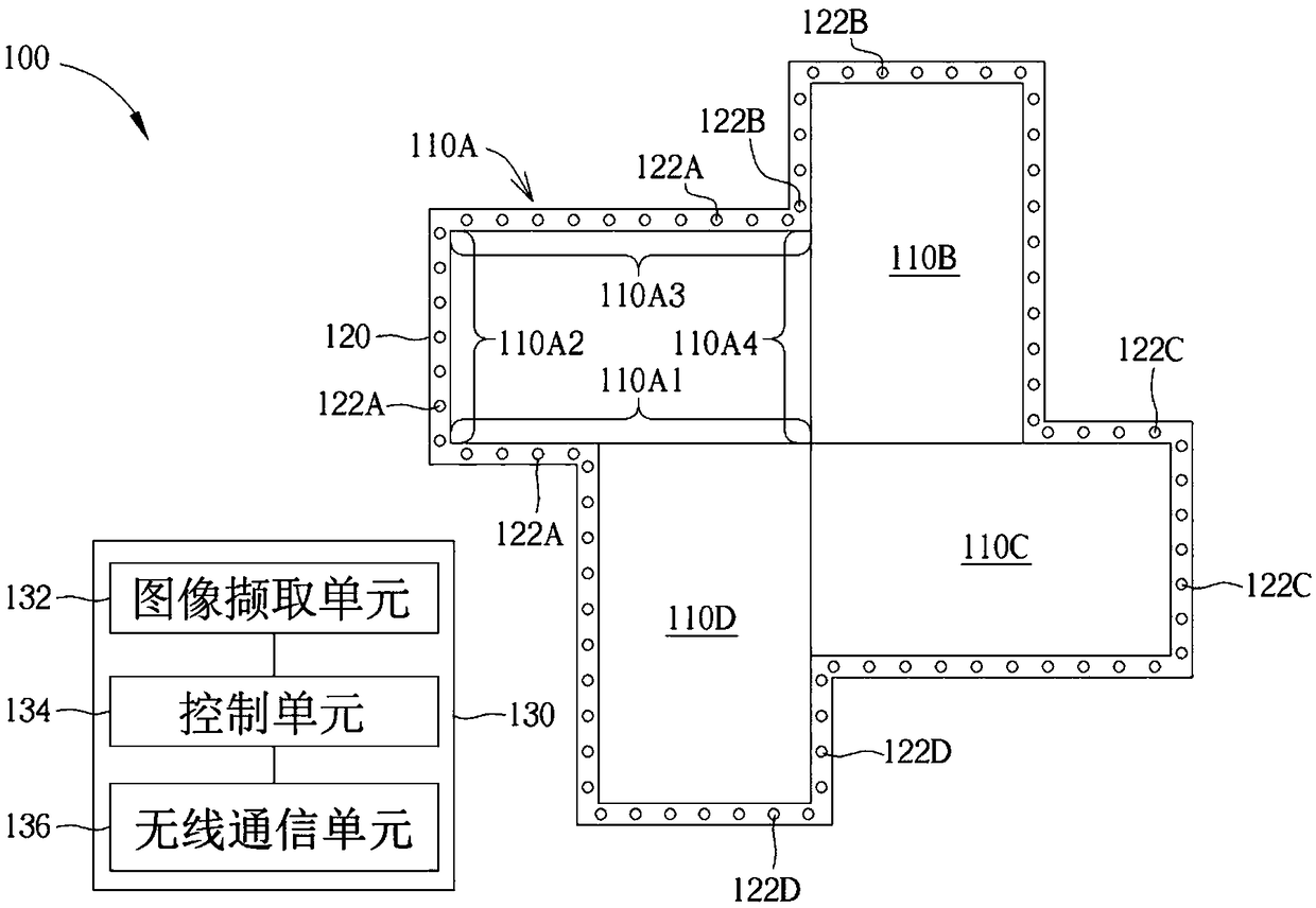
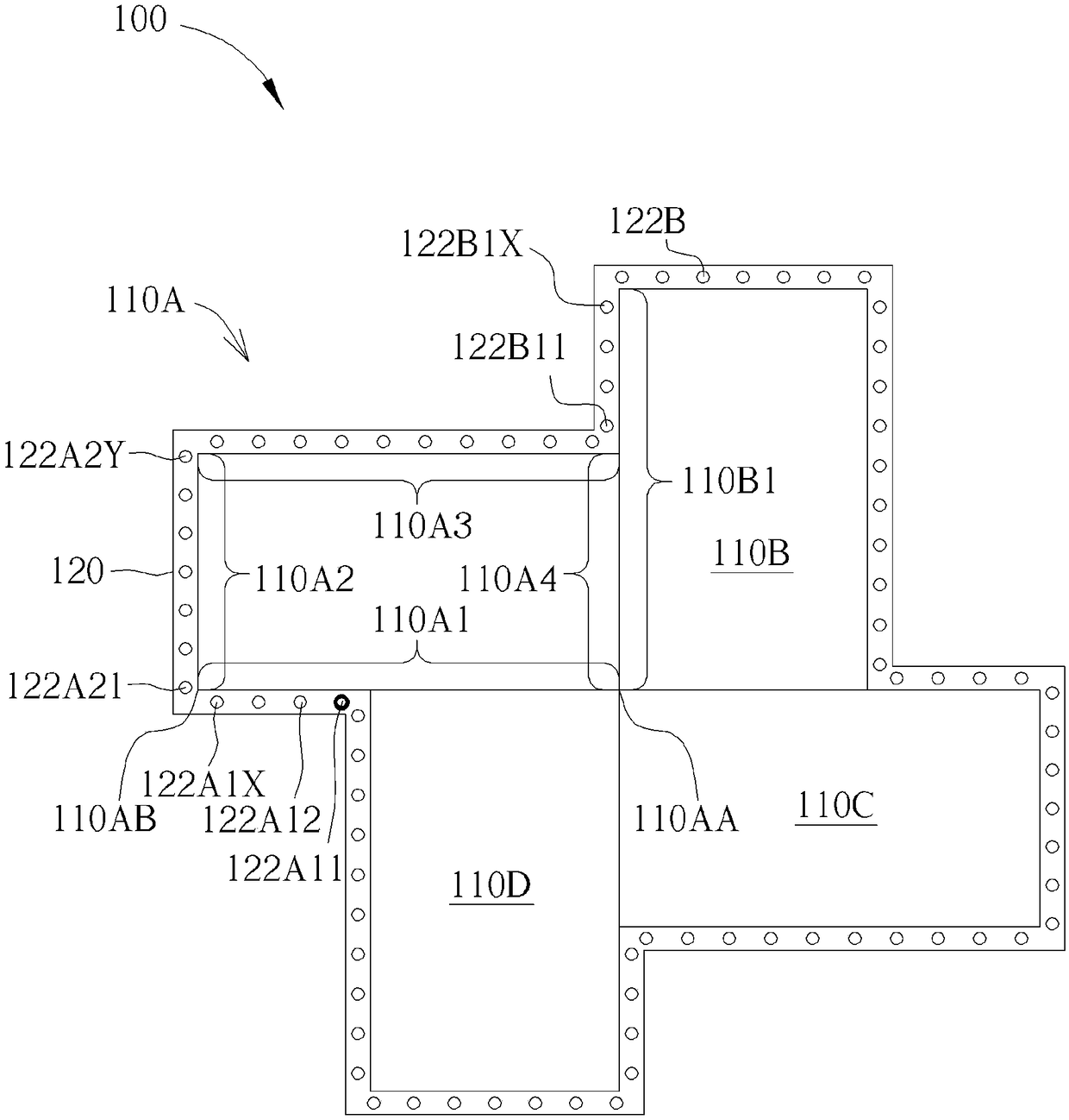
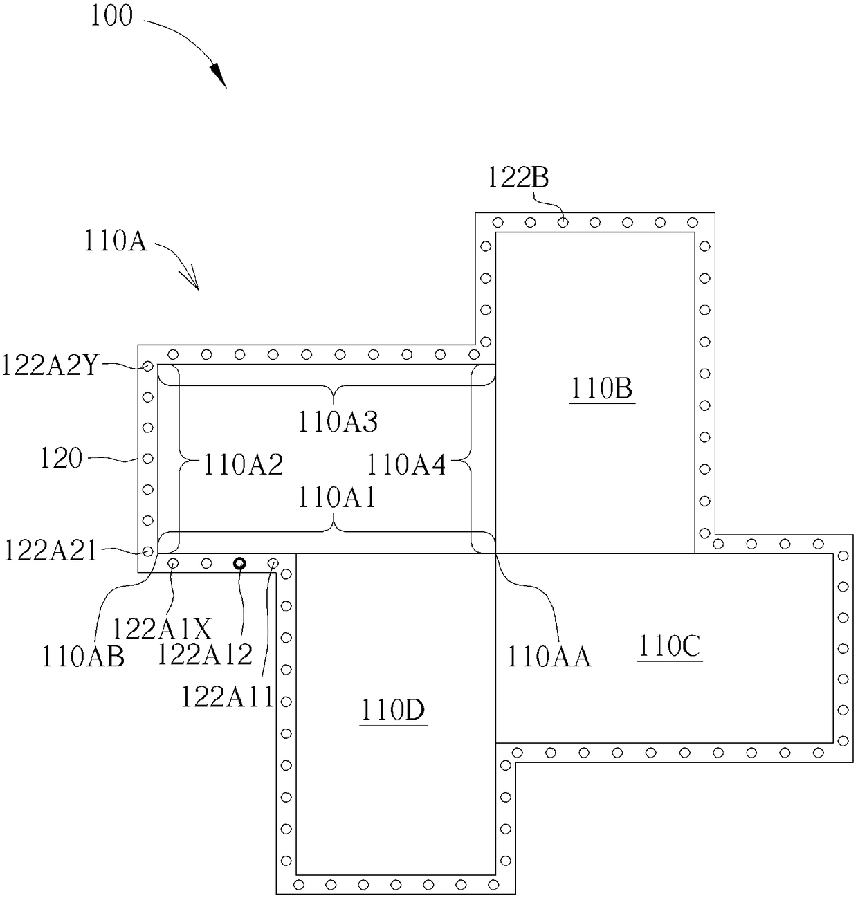
[0031] figure 1 A display system 100 of an embodiment of the invention is shown. The display system 100 includes a first display 110A, a first light bar 120 and an electronic device 130 .

[0032] The first light bar 120 includes a plurality of light emitting units 122A disposed along the edge of the first display 110A. For example, some light emitting units 122A are disposed along a portion of the first edge 110A1 of the first display 110A. The electronic device 130 includes an image capture unit 132 and a control unit 134 , and the control unit 134 is coupled to the image capture unit 132 . In some embodiments, the light emitting units 122A˜ 122D of the first light bar 120 may be light emitting diodes. Also, in some embodiments, electronic device 130 may be, for...


PUM


Abstract

The invention discloses a display system which comprises a first display, a first light bar and electronic equipment. The first display displays a first image. The first light bar comprises a plurality of lighting units which are arranged at one part of the first edge of the first display. The electronic equipment comprises an image capturing unit and a control unit. Whenever the light unis of thefirst light bar are started, the image capturing unit captures the images of the first display and the first light bar. The control unit recognizes at least the first lighting unit and the last lighting unit of the first light bar along the first edge of the first display, and the relative positions of the first lighting unit and the last lighting unit are generated according to the images captured by the image capturing unit. According to the display system and a method used for operating the display system, the configuration of the lamp bar and the display screen of the display system is simplified, and the visual effect is improved.

Description

technical field [0001] The invention relates to a display system, and further relates to a display system with light bars arranged along the edge of the display. Background technique [0002] With the development of display technology, more and more visual effects are created. For example, video walls built from multiple TV displays can present large-scale images and are widely used in concerts, exhibitions, and malls to display real-time performances and commercials. The huge size images displayed on the video wall can provide exciting visual effects and attract customers. [0003] And, to create even more exciting and novel visual effects, TV displays can also be combined with other devices such as light bars that surround the TV display. However, these display devices require different numbers of screens and form video walls with different sizes and shapes in order to meet venue requirements. Therefore, the setting of the display device is complicated and requires a lo...

Claims


Application Information

Patent Timeline
Patent Type & Authority Applications(China)
IPC IPC(8): G09F9/302G06F3/14
CPCG06F3/1446G09F9/3026G09G3/2003G09G3/342G09G2300/026G09G2310/024G09G2360/145G09G5/02G09G5/10G09G2320/062G09G2320/08G09G2370/16
Inventor 陈威州
Owner QISDA SUZHOU
Learn More