
A low profile LTCC millimeter wave dual polarization antenna

A dual-polarized antenna and millimeter-wave technology, which is applied in the direction of slot antenna, antenna grounding switch structure connection, circuit, etc., can solve the problems that microstrip line reduces antenna efficiency, is difficult to obtain wide application, and cannot have both broadband and other problems, and achieves Realize the effect of broadening the operating frequency band, high gain, and suppressing the surface wave of the substrate

Inactive Publication Date: 2018-12-21
HUAZHONG UNIV OF SCI & TECH
View PDF5 Cites 22 Cited by
  • Summary
  • Abstract
  • Description
  • Claims
  • Application Information

AI Technical Summary

Problems solved by technology

[0005] Aiming at the defects of the prior art, the purpose of the present invention is to solve the problem that the huge loss of the microstrip line of the existing dual-polarized antenna in the millimeter wave frequency band will greatly reduce the efficiency of the antenna, and it is difficult to obtain wide application. Technical Issues of Isolation and Low Profile Advantages

Method used


Image

  • A low profile LTCC millimeter wave dual polarization antenna
  • A low profile LTCC millimeter wave dual polarization antenna
  • A low profile LTCC millimeter wave dual polarization antenna

Examples


Embodiment Construction

[0033] In order to make the object, technical solution and advantages of the present invention clearer, the present invention will be further described in detail below in conjunction with the accompanying drawings and embodiments. It should be understood that the specific embodiments described here are only used to explain the present invention, not to limit the present invention. In addition, the technical features involved in the various embodiments of the present invention described below can be combined with each other as long as they do not constitute a conflict with each other.

[0034] The purpose of the present invention is to provide a low-profile LTCC millimeter-wave dual-polarized antenna, aiming at realizing high gain, wide frequency band and high isolation of dual ports at a low profile height. The invention is based on the multi-layer planar technology of LTCC. By adopting the radiation structure of the substrate integrated cavity, the high-order mode of the cavi...


PUM

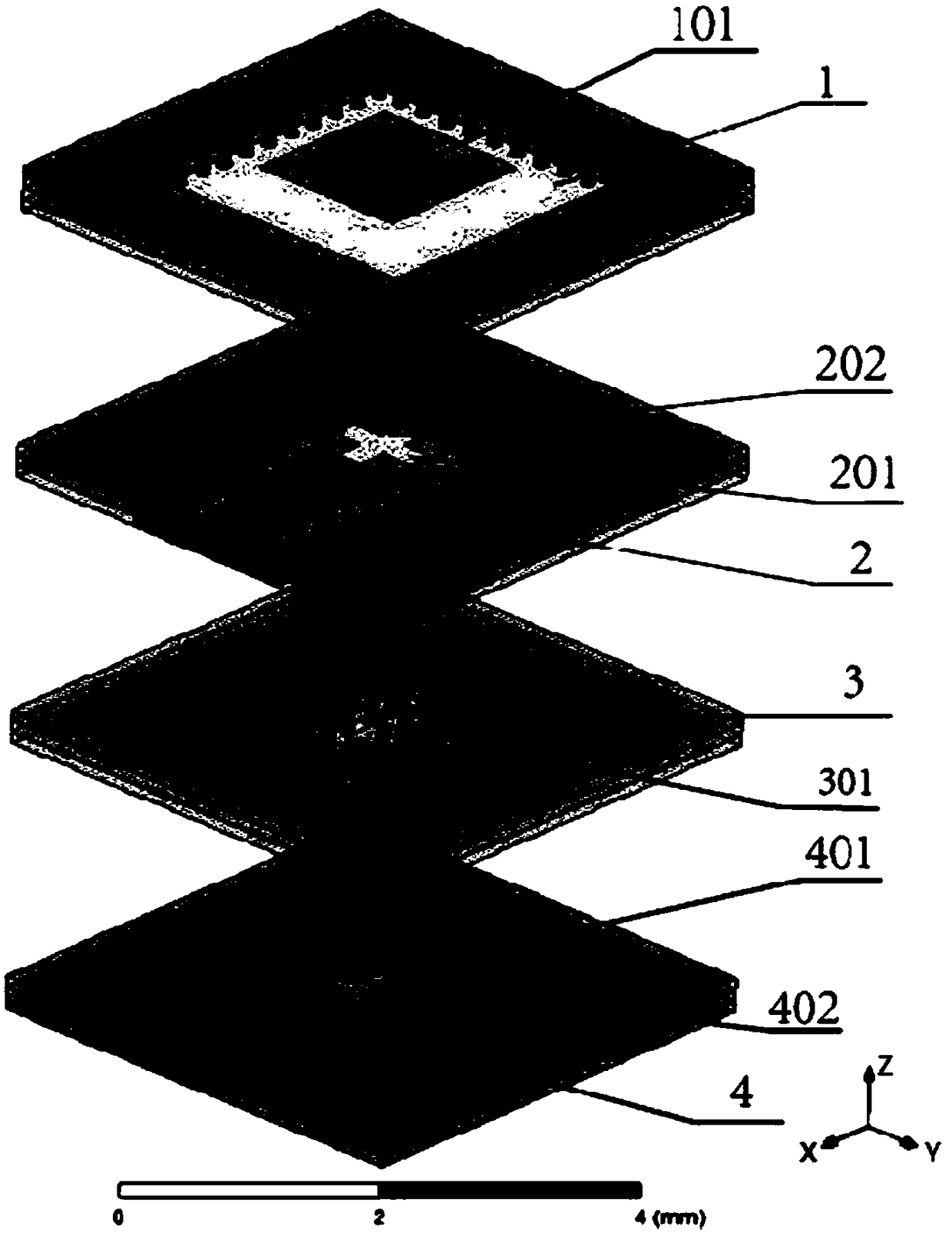
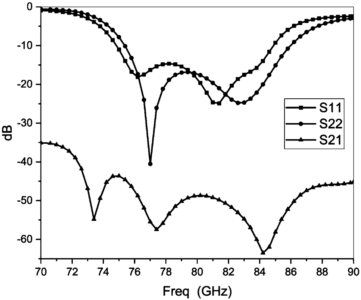
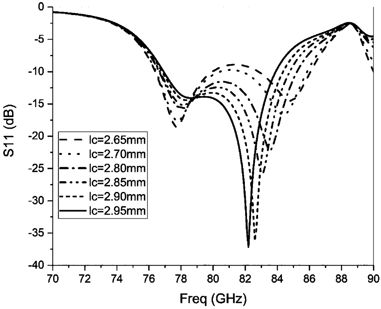

Abstract

The invention discloses a low-profile LTCC millimeter wave dual-polarization antenna, comprising: a first slot and a second slot crossing each other are arranged on the lower surface of a substrate integrated cavity; The lower surface of the upper waveguide is provided with a third slot; A low surface of that transition structure is provided with a fourth gap; The electromagnetic wave input from the first port is transmitted in the upper substrate integrated waveguide, coupled into the substrate integrated cavity through the first slot, and polarized in the first direction. The electromagneticwave input from the second port is transmitted through the lower waveguide, coupled into the upper waveguide through the fourth and third slots, coupled into the substrate integrated cavity through the second slot, and polarized in the second direction. When the antenna receives the electromagnetic wave in the first direction, the electromagnetic energy enters the upper waveguide through the first slot. As that antenna receive the electromagnetic wave in the second direction, the electromagnetic energy enters the upper substrate integrate waveguide through the second slot and is coupled intothe lower waveguide through the third and fourth slots. The invention realizes high gain, wide frequency band and high isolation of the bipolar antenna.

Description

technical field [0001] The present invention relates to the technical field of millimeter-wave antennas, and more particularly, to a low-profile low-temperature co-fired ceramic (Low Temperature Co-fired Ceramic, LTCC) millimeter-wave dual-polarization antenna. Background technique [0002] With the continuous development of wireless communication, the spectrum resources of microwave and below are increasingly tight. To solve this problem, people gradually shift their attention to the millimeter wave frequency band. Compared with the microwave frequency band, millimeter wave has the advantages of wide frequency band, narrow beam, fast transmission rate, strong detection ability, strong anti-interference ability, and good penetration. This makes mmWave systems widely used in high-speed data transmission, space communication, precision guidance, and high-resolution imaging radar. As a key component in a millimeter wave system, the performance of the millimeter wave antenna de...

Claims


Application Information

Patent Timeline
Patent Type & Authority Applications(China)
IPC IPC(8): H01Q1/36H01Q1/38H01Q1/50H01Q13/10
CPCH01Q1/38H01Q1/36H01Q1/50H01Q13/10
Inventor 王晓川秦德超吕文中范桂芬雷文梁飞汪小红付明
Owner HUAZHONG UNIV OF SCI & TECH
Learn More