Supercharge Your Innovation With Domain-Expert AI Agents!

A method and system for optimal configuration of medium-voltage distribution network capacitors based on reactive power partitioning

An optimized configuration and capacitor technology, applied in reactive power compensation, circuit devices, AC network circuits, etc., can solve the problems of small reactive load to be compensated, large number of nodes to be compensated, large reactive load to be compensated, etc.

Inactive Publication Date: 2020-04-21
国网西藏电力有限公司拉萨供电公司
View PDF5 Cites 0 Cited by
  • Summary
  • Abstract
  • Description
  • Claims
  • Application Information

AI Technical Summary

Problems solved by technology

However, the reactive second precise moment of each node is calculated with the root node as the only reactive power point, without considering the situation of multiple reactive power points after compensation, which will easily cause the reactive power partition at the end of the feeder to be compensated. The reactive power load is small, It is easy to lead to a small number of nodes to be compensated, and the total reactive power load to be compensated in the reactive power zone close to the root node is large, which may easily lead to a large number of nodes to be compensated. As a result, when the compensation point is determined in units of reactive power zones, the reactive power The number of compensation nodes that can be selected in the partition may be small, which reduces the range of point selection and affects the compensation effect, especially for long-distance feeder lines
[0006] In addition, on the basis of partitions, a compensation point is set in each reactive power partition to reduce the understanding space. However, it is still necessary to use an intelligent optimization algorithm to solve the position and capacity of the compensation point in each partition at the same time, and the calculation efficiency is low, which affects Practical application of the method

Method used


Image

  • A method and system for optimal configuration of medium-voltage distribution network capacitors based on reactive power partitioning
  • A method and system for optimal configuration of medium-voltage distribution network capacitors based on reactive power partitioning
  • A method and system for optimal configuration of medium-voltage distribution network capacitors based on reactive power partitioning

Examples


Embodiment Construction

[0047] It should be pointed out that the following detailed description is exemplary and intended to provide further explanation to the present application. Unless defined otherwise, all technical and scientific terms used herein have the same meaning as commonly understood by one of ordinary skill in the art to which this application belongs.

[0048] It should be noted that the terminology used here is only for describing specific implementations, and is not intended to limit the exemplary implementations according to the present application. As used herein, unless the context clearly dictates otherwise, the singular is intended to include the plural, and it should also be understood that when the terms "comprising" and / or "comprising" are used in this specification, they mean There are features, steps, operations, means, components and / or combinations thereof.

[0049] A method for optimal configuration of medium-voltage distribution network capacitors based on reactive po...


PUM


Abstract

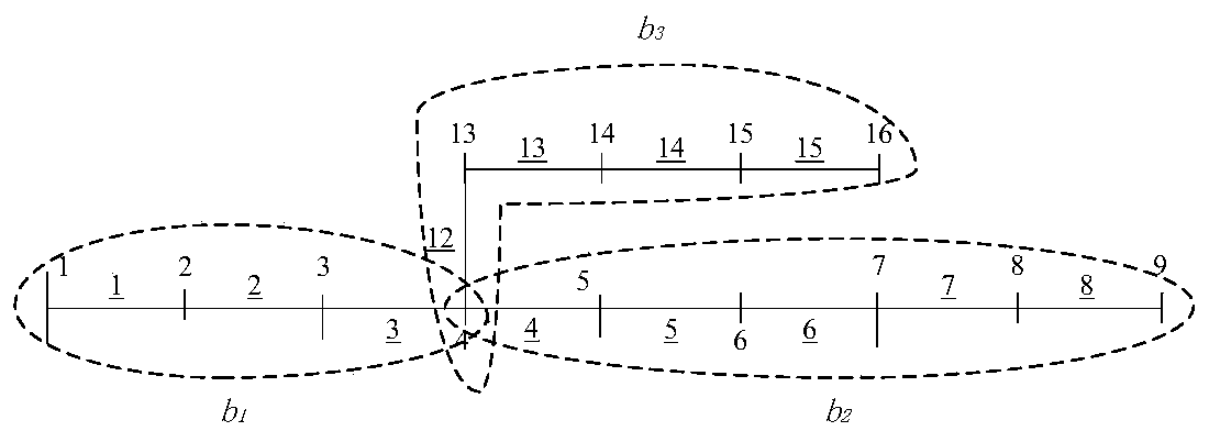
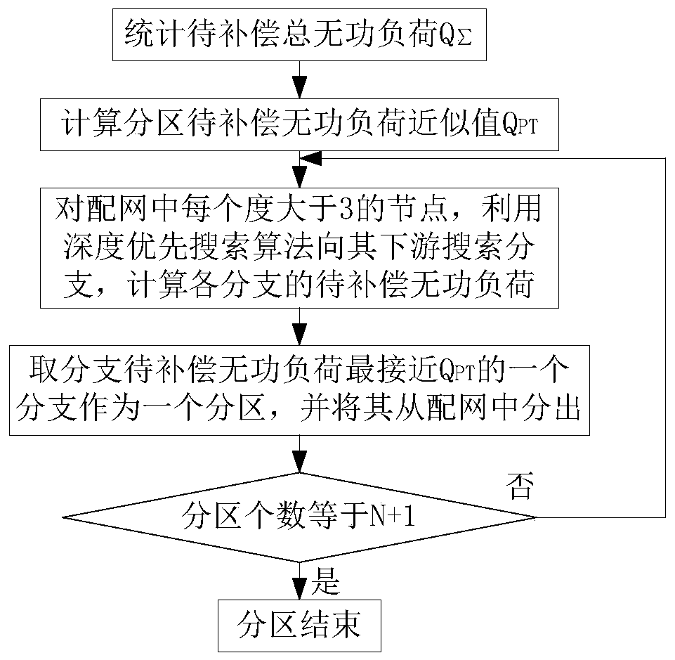
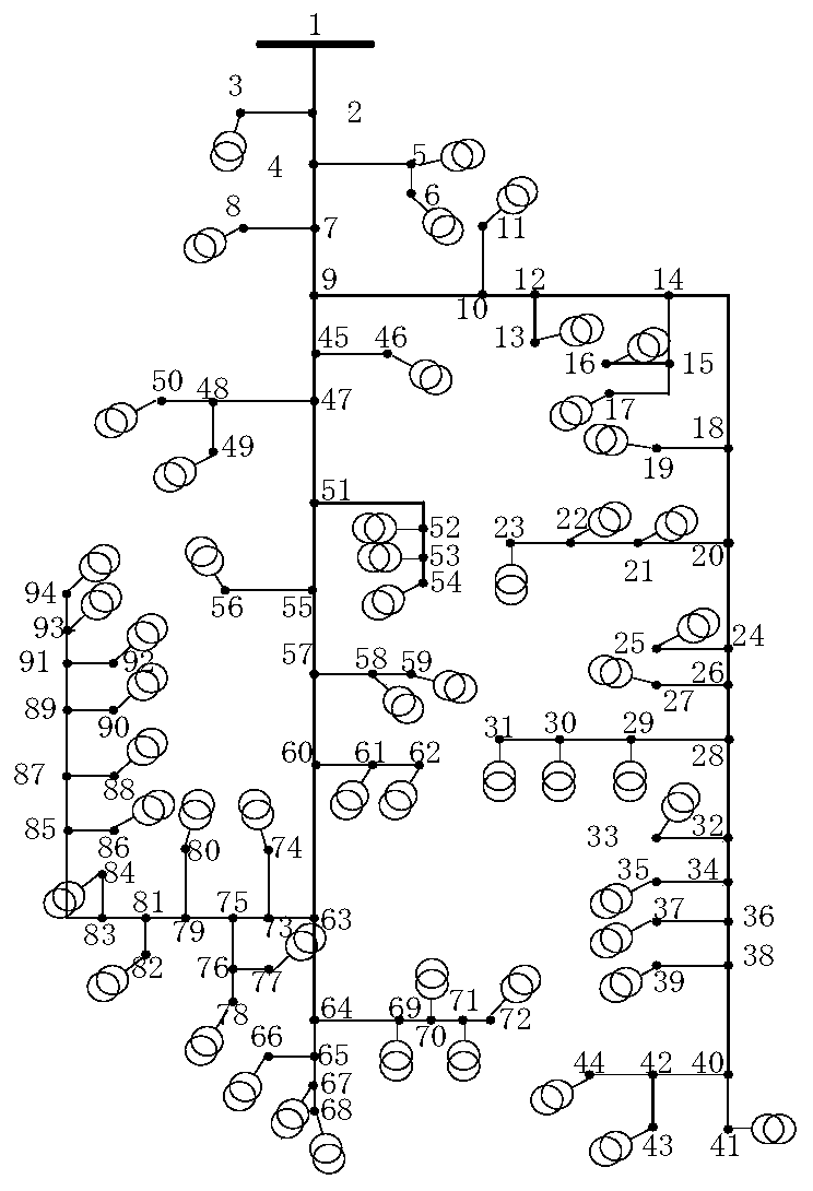
The invention discloses a medium-voltage distribution network capacitor optimal configuration method and system based on reactive power division. Firstly, the medium-voltage distribution network is divided based on a depth-first search algorithm and a reactive load maximum approximation principle of each division, so that the number of nodes in each reactive power division is maximally approximated, which is favorable for optimizing compensation point position based on reactive power division. For the reactive power zoning, it is helpful to optimize the position and capacity of compensation point based on the method of cut-off optimization and range of action, which can improve the economic benefit of compensation. Finally, an actual 94-node feeder verifies the superiority and practicability of the algorithm.

Description

technical field [0001] The invention relates to the technical field of shunt capacitor configuration in a medium-voltage distribution network, in particular to a method and system for optimally configuring capacitors in a medium-voltage distribution network based on reactive power partitions. Background technique [0002] The shunt capacitor configuration of the medium-voltage distribution network is to determine the number, location and group number of compensation points on the 10kV feeder, which can effectively improve the voltage distribution, reduce network loss, release the transmission capacity of the feeder, and improve economic benefits. If the research on this problem is combined with the following two characteristics, a better compensation effect will be obtained: 1) the radial structure of the distribution network; 2) reactive power cannot be transmitted on a large scale and over long distances. [0003] The shunt capacitor configuration of the medium voltage dis...

Claims


Application Information

Patent Timeline
Patent Type & Authority Patents(China)
IPC IPC(8): H02J3/18
CPCH02J3/18H02J3/1871H02J2203/20Y02E40/30
Inventor 覃文继达娃伦珠杨震涛漆炜之王晓庆陶魁尼平薛小刚潘志远杨维尹亮亮巴桑顿珠贺阳杨翔格桑尼玛扎西顿珠苏延香
Owner 国网西藏电力有限公司拉萨供电公司
Features
  • R&D
  • Intellectual Property
  • Life Sciences
  • Materials
  • Tech Scout
  • Unparalleled Data Quality
  • Higher Quality Content
  • 60% Fewer Hallucinations
Learn More