Disc motor, stator core of disk motor, and method for manufacture the stator core

A technology of stator iron core and disc motor, which is applied in the manufacture of motor generators, stator/rotor bodies, electrical components, etc., can solve the problems of reduced efficiency, increased loss of motor iron core, and poor electromagnetic performance.

Pending Publication Date: 2018-12-21
SHANGHAI PANGOOD POWER TECH CO LTD
View PDF0 Cites 1 Cited by
  • Summary
  • Abstract
  • Description
  • Claims
  • Application Information

AI Technical Summary

Problems solved by technology

[0008] However, the cost of soft magnetic composite materials is 3 to 4 times that of silicon steel sheets, and the cost of powder pressing molds is also relatively expensive; the electromagnetic properties of soft magnetic composite materials are worse than those of silicon steel sheets, resulting in increased core loss and reduced efficiency of motors

Method used


Image

  • Disc motor, stator core of disk motor, and method for manufacture the stator core
  • Disc motor, stator core of disk motor, and method for manufacture the stator core
  • Disc motor, stator core of disk motor, and method for manufacture the stator core

Examples


Embodiment Construction

[0034] The invention discloses a stator core of a disc motor, which reduces the difficulty of preparing the iron core of the disc motor; the invention also provides a disc motor; the invention also provides a stator core of the disc motor Manufacturing method.

[0035] The technical solutions in the embodiments of the present invention will be clearly and completely described below in conjunction with the accompanying drawings in the embodiments of the present invention. Obviously, the described embodiments are only some, not all, embodiments of the present invention. Based on the embodiments of the present invention, all other embodiments obtained by persons of ordinary skill in the art without making creative efforts fall within the protection scope of the present invention.

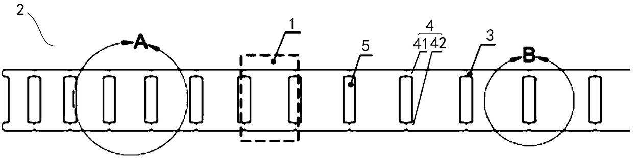
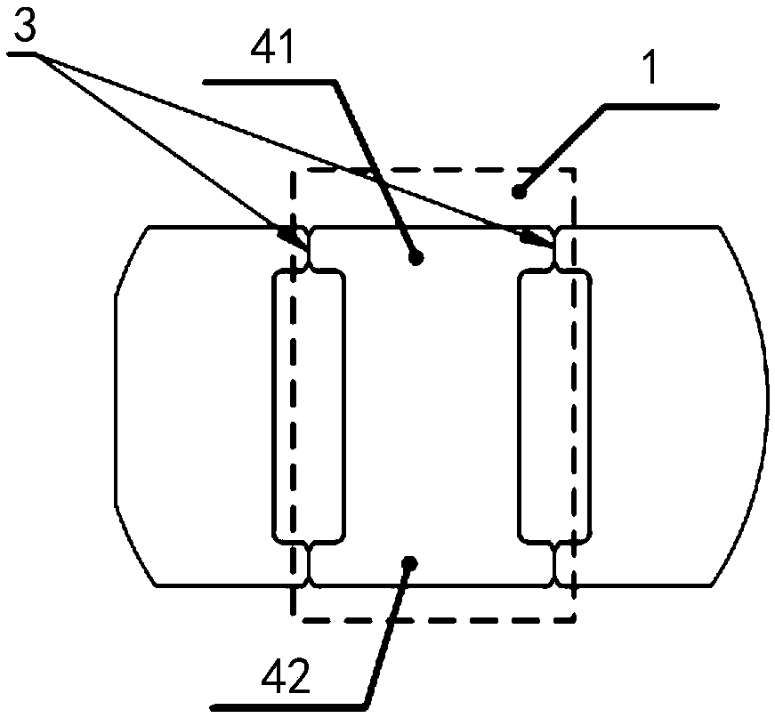
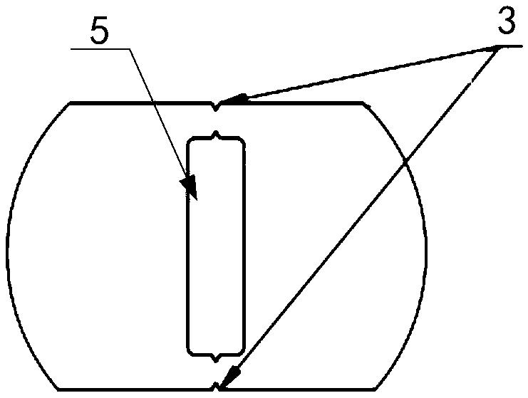
[0036] like Figure 1-Figure 3 as shown, figure 1 A schematic diagram of the first expanded structure of the segmented iron core in the stator iron core of the disc motor provided by the present inve...


PUM


Abstract

The invention provides a stator iron core of a disc motor. The segmented iron core comprises a plurality of iron core units connected end to end and arranged in a stack. The plurality of iron core units are non-equidistant iron core units formed on the length direction of the same iron core strip and arranged in a gradually increasing width. Between any two adjacent iron core units, a crease groove is arranged to limit the position of the crease groove. A plurality of iron core units are formed on the same iron core strip, and the widths of the iron core strip are gradually increased in the longitudinal direction, and the iron core units are laminated in a trapezoidal structure by folding and laminating mode. During the processing of the core strip, the non-equidistant core unit can be processed on the core strip by stamping the crease groove of the predetermined structure, and the segmented iron core with the trapezoidal structure can be directly formed through the folding and compression procedures, thus reducing the processing difficulty and cost of the segmented iron core. The invention also provides a manufacturing method of a disc motor and a stator iron core thereof.

Description

technical field [0001] The invention relates to the field of motors, more specifically, to a disc motor, a stator core of the disc motor and a manufacturing method thereof. Background technique [0002] Disc motors are also called axial field motors. The direction of the magnetic field inside the motor is along the axial direction, and axial field motors are generally flat. [0003] For the manufacture of most iron cores of motors, silicon steel sheets, amorphous alloys, powder metallurgy and other types of magnetic permeable alloy materials are generally used, among which silicon steel sheet iron cores account for a large proportion. For conventional radial field motors, the motor iron core is formed by stamping and stacking silicon steel sheets, but for disc motors, since the magnetic field direction is axial, it cannot be realized by conventional iron core technology. [0004] The iron core of the disc motor is divided into an integral iron core and a segmented iron core...

Claims


Application Information

Patent Timeline
Patent Type & Authority Applications(China)
IPC IPC(8): H02K1/14H02K15/02
CPCH02K1/148H02K15/022
Inventor 汤磊夏莉
Owner SHANGHAI PANGOOD POWER TECH CO LTD
Why Eureka
Try Eureka