
Turbine for an exhaust turbocharger having a dual branch turbine housing and valve arrangement for branch connection and waste gate control

A technology of turbine housing and exhaust gas turbine, which is applied to valve devices, machines/engines, lift valves, etc., can solve the problem that the shape of the valve body 36 cannot be freely selected, and achieve thermal deformation compensation and reduce space requirements. Effect

Active Publication Date: 2018-12-21
VTESCO TECH GMBH
View PDF8 Cites 0 Cited by
  • Summary
  • Abstract
  • Description
  • Claims
  • Application Information

AI Technical Summary

Problems solved by technology

This has the disadvantage that, for example, the shape of the valve body 36 cannot be freely selected and cannot be cylindrical, for example

Method used


Image

  • Turbine for an exhaust turbocharger having a dual branch turbine housing and valve arrangement for branch connection and waste gate control
  • Turbine for an exhaust turbocharger having a dual branch turbine housing and valve arrangement for branch connection and waste gate control
  • Turbine for an exhaust turbocharger having a dual branch turbine housing and valve arrangement for branch connection and waste gate control

Examples


Embodiment Construction

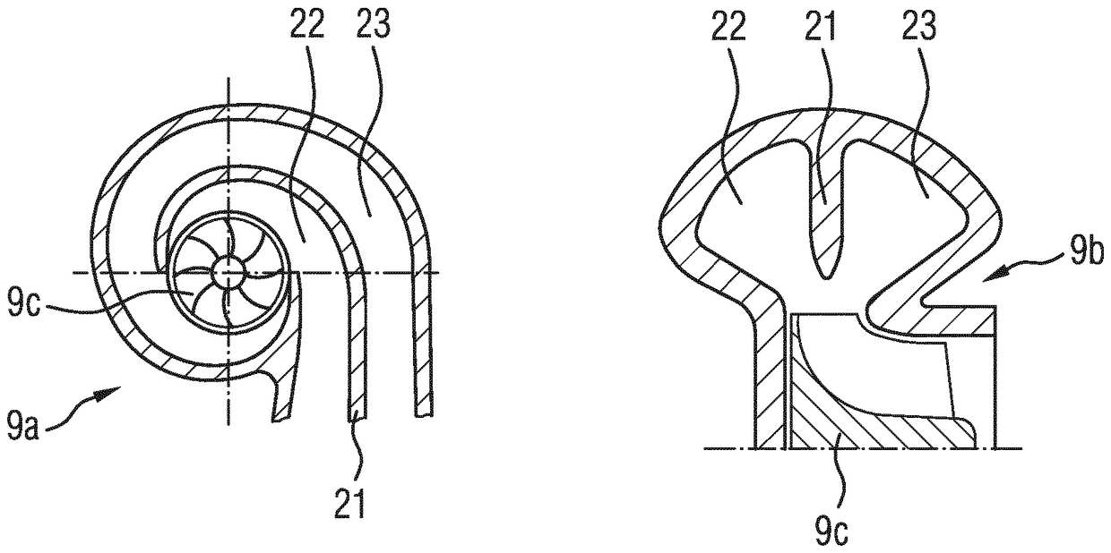
[0030] To explain the first exemplary embodiment, Figure 9 Details of the turbine housing are shown in cross-section.

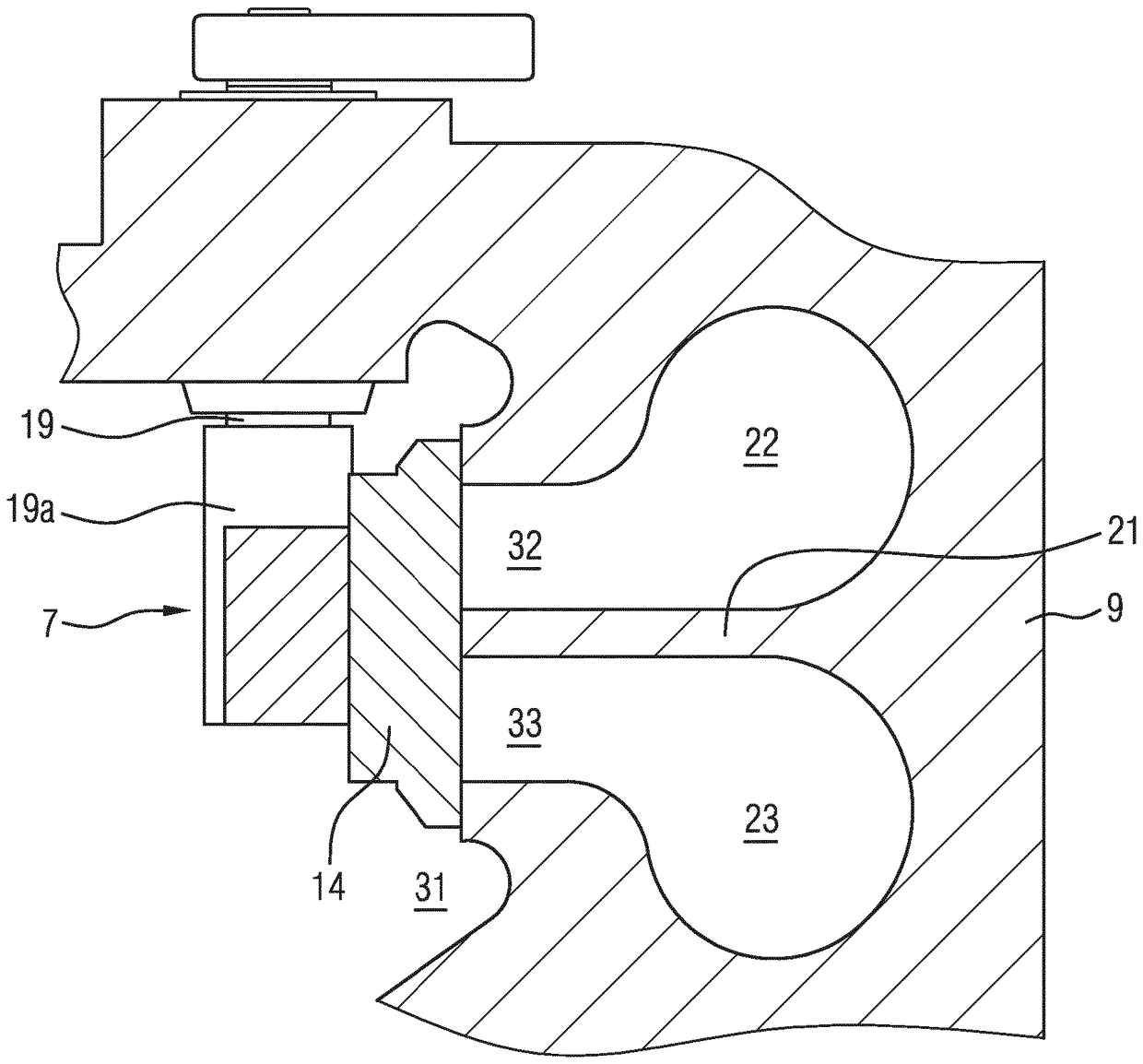
[0031] In this first exemplary embodiment, two exhaust gas volutes 22 , 23 are arranged in the turbine housing 9 , through which exhaust gas can flow. The partition wall 21 is located between the two exhaust gas volutes 22 , 23 . Furthermore, the turbine housing 9 has an outlet opening 31 through which a part of the exhaust gas mass flow escapes when the wastegate opening is open. Furthermore, in the exemplary embodiment shown, a linear valve with a valve element 35 is provided.

[0032] In order to close the wastegate opening 13, the valve element 35 is guided from the outlet chamber 31 in the direction of the valve seat 13a, and in order to open the wastegate opening 13, the valve element 35 can be lifted from the valve seat 13 via the displacement shaft 30 in the longitudinal direction of the shaft The axial direction of the axis 30 a enters the outlet...


PUM


Abstract

The invention relates to a turbine (3) for an exhaust turbocharger (2) having a turbine housing (9), which has two exhaust branches (22, 23), through which an exhaust mass flux can flow, and between which a partition (21) is provided, and having a linear valve, which has a valve element (35) and an adjustment shaft (30), wherein the adjustment shaft (30) is guided through the partition (21) and ismovably arranged in the direction of the shaft longitudinal axis (30a) in the partition (21), and wherein the adjustment shaft (30) and the valve element (35) are separate components, which are connected to each other such that an equalization of positional and dimensional tolerances between the adjustment shaft (30) and the valve element (35) in operation is enabled.

Description

technical field [0001] The invention relates to a turbine for an exhaust gas turbocharger having a double volute turbine housing and a valve arrangement for volute connection and wastegate control. Background technique [0002] The internal combustion engine 1 supercharged by the exhaust gas turbocharger 2 is characterized in that figure 1 Fresh air and exhaust air are introduced to the unit as shown. During supercharged operation, exhaust gases flow from the internal combustion engine 1 via a turbine 3 , which drives a compressor 4 via a common shaft 5 in the intake tract upstream of the inlet of the engine 1 . Due to the compression of the intake air, more fuel can be mixed per cylinder stroke, so the torque of the engine 1 increases. [0003] For clarity, some elements of the air guide are in figure 1 not shown in These elements are, for example, an air filter arranged upstream of the compressor, an air flow sensor arranged upstream of the compressor, a charge air coo...

Claims


Application Information

Patent Timeline
Patent Type & Authority Applications(China)
IPC IPC(8): F02B37/02F02B37/18F16K1/20F01D17/10F02B37/22
CPCF01D17/105F02B37/183F02B37/186F02B37/225F05D2220/40F16K1/48F16K11/052F02B37/025Y02T10/12F16K1/2014F05D2260/60
Inventor C.施帕雷尔
Owner VTESCO TECH GMBH
Learn More