Supercharge Your Innovation With Domain-Expert AI Agents!

Scroll compressor

A scroll compressor and scroll technology, applied in the field of compressors, can solve the problems of back pressure chamber delay, pressure leakage, reduction of sealing force, etc., and achieve the effects of improving sealing effect, improving compression efficiency and reducing weight

Active Publication Date: 2018-12-21
LG ELECTRONICS INC
View PDF7 Cites 4 Cited by
  • Summary
  • Abstract
  • Description
  • Claims
  • Application Information

AI Technical Summary

Problems solved by technology

[0015] However, in the prior art lower compression type scroll compressor as described above, the sealing member 36 is formed in a ring shape having the cutout portion 36a, but this may cause pressure leakage through the cutout portion 36a, and accordingly Unable to keep the pressure in the back pressure chamber S constant
[0016] Also, if the pressure in the back pressure chamber S is not constant, the behavior of the orbiting scroll 33 becomes unstable, thereby reducing the pressure on the compression chamber V between the orbiting scroll 33 and the fixed scroll 32. Sealing force will be reduced, resulting in loss of compression
[0017] Also, when applied to a high compression ratio compressor, the reliability of the cutout portion 36a will be reduced, so that there is also a risk that the sealing member 36 will be damaged.
[0018] Also, as the sealing member 36 is formed into a quadrangular cross-sectional shape, it causes an increase in the weight of the sealing member 36 as a whole, and at the time of initial operation, the sealing member 36 will not be able to float quickly, so there is also a possibility that the formation of the back pressure chamber is delayed. question
[0019] Furthermore, when the axial thickness of the sealing member 36 is formed thin, not only the sealing area in the radial direction is reduced, but also its life is shortened due to wear with the main frame 31. On the other hand, when the radial width is formed thin When this happens, not only the sealing area in the axial direction is reduced, but also the pressure-bearing area that bears the weight is reduced, which leads to the problem that the suspension is delayed

Method used


Image

  • Scroll compressor
  • Scroll compressor
  • Scroll compressor

Examples


Embodiment Construction

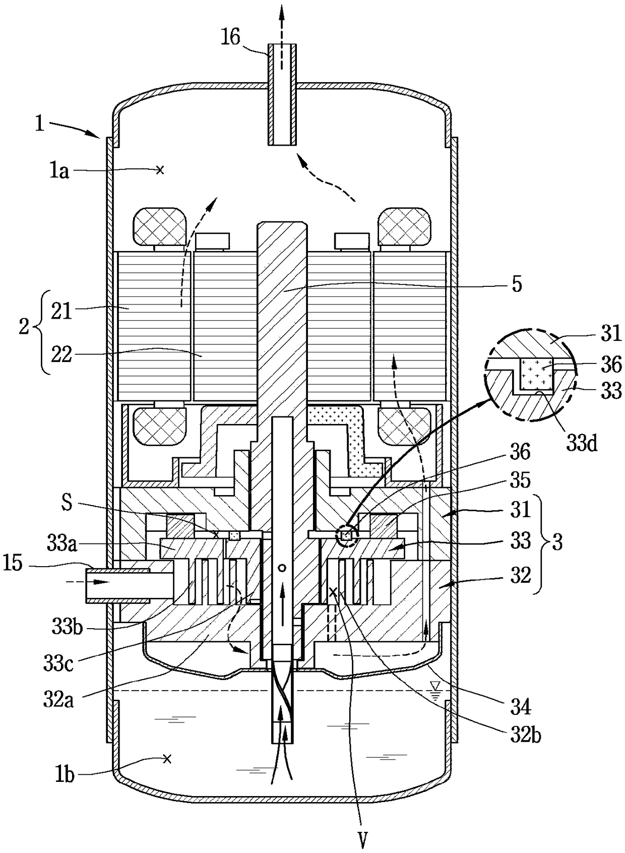
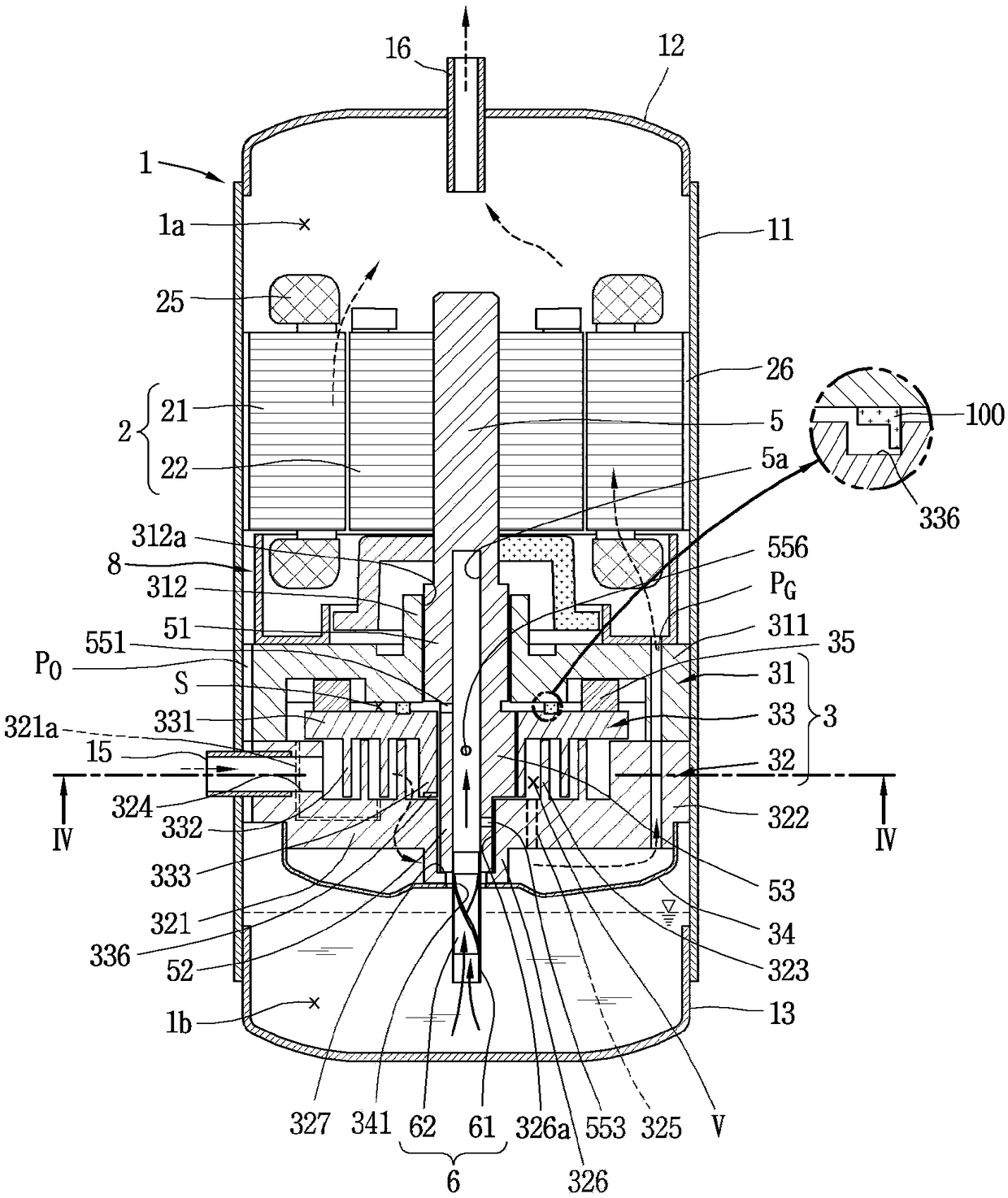
[0062] Hereinafter, the scroll compressor of the present invention will be described in detail with reference to an embodiment shown in the accompanying drawings. For reference, the scroll compressor of the present invention relates to a structure for improving sealing force and durability of a sealing member provided between an orbiting scroll and a corresponding main frame to form a back pressure chamber. Therefore, the scroll compressor having the sealing member between the members in contact with the orbiting scroll can be applied to any type of scroll compressor. However, in the following, for the convenience of description, in the lower compression type scroll compressor in which the compression part is located below the electric part, the scroll of the type in which the rotating shaft and the orbiting scroll part overlap on the same plane The type compressor is described as a representative example. Such a type of scroll compressor is known to be suitable for use in a ...


PUM


Abstract

A scroll compressor according to the present invention comprises: a motor unit providing driving force; an orbiting scroll made to orbit by the motor unit; a fixed scroll coupled to the orbiting scroll to define a compression chamber together with the orbiting scroll; a frame coupled to the fixed scroll to support the orbiting scroll; a sealing member insertion groove having a ring shape and formed on a first facing surface of the frame, which contacts the orbiting scroll, or on a second facing surface of the orbiting scroll, which contacts the frame; and a sealing member. The sealing member comprises: a first sealing part formed in a ring shape and inserted into the sealing member insertion groove so as to be movable in a shaft direction, thereby sealing the shaft direction between the frame and the orbiting scroll; and a second sealing part extending from the first sealing part in the shaft direction, contacting an external wall surface of the sealing member insertion groove to seala radial direction, and having a radial direction thickness less than the shaft direction thickness of the first sealing part.

Description

technical field [0001] The present invention relates to a scroll compressor, in particular to a compressor in which a compression section is located below an electric section. Background technique [0002] Generally speaking, the scroll compressor can obtain a relatively high compression ratio compared with other types of compressors, and can achieve stable torque by gently realizing the suction, compression, and discharge strokes of the refrigerant, because of its above-mentioned Due to the advantages described above, scroll compressors are widely used in air conditioners and the like for compressing refrigerant. [0003] The behavior characteristics of the scroll compressor are composed of the non-orbiting scroll (hereinafter referred to as the fixed scroll) (scroll), the non-orbiting scroll (hereinafter referred to as the fixed scroll) (wrap) and the orbiting scroll It is determined by the shape of the spiral wrap portion of the disk. Although the fixed wrap and the orb...

Claims


Application Information

Patent Timeline
Patent Type & Authority Applications(China)
IPC IPC(8): F04C18/02F04C27/00F04C29/02
CPCF04C23/008F04C27/008F04C18/0253F04C18/0215F04C27/005F01C19/005F04C27/001F04C29/02F04C2240/40F04C2240/30F04C2240/603
Inventor 李浩源崔重善金哲焕
Owner LG ELECTRONICS INC
Features
  • R&D
  • Intellectual Property
  • Life Sciences
  • Materials
  • Tech Scout
  • Unparalleled Data Quality
  • Higher Quality Content
  • 60% Fewer Hallucinations
Learn More