
Screw compressor

一种螺旋压缩机、压缩机壳体的技术,应用在螺旋压缩机领域,达到易激活的效果

Active Publication Date: 2018-12-21
BITZER KUEHLMASCHINENBAU GMBH
View PDF7 Cites 0 Cited by
  • Summary
  • Abstract
  • Description
  • Claims
  • Application Information

AI Technical Summary

Problems solved by technology

[0003] In this screw compressor there is the problem of being able to realize the transition of the control slide valve from the connected position to the disconnected position as reliably as possible starting from the different connecting positions along the slide valve channel.

Method used


Image

  • Screw compressor
  • Screw compressor
  • Screw compressor

Examples


Embodiment Construction

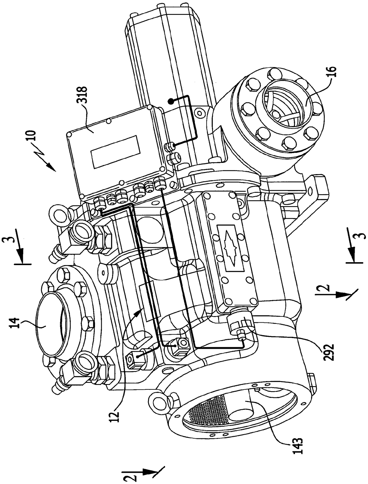
[0058] figure 1 The screw compressor 10 according to the invention of the embodiment shown in includes a compressor housing indicated as a whole by 12, which has a suction connection 14 and a pressure connection 16, through which the suction to be sucked The gaseous medium, especially the refrigerant, is discharged via the pressure connection to the gaseous medium, especially the refrigerant, which is compressed to high pressure.

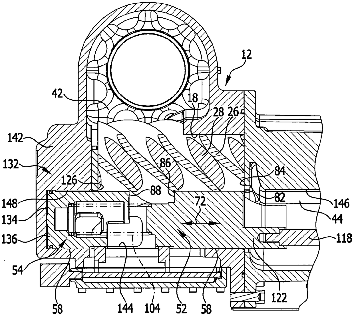
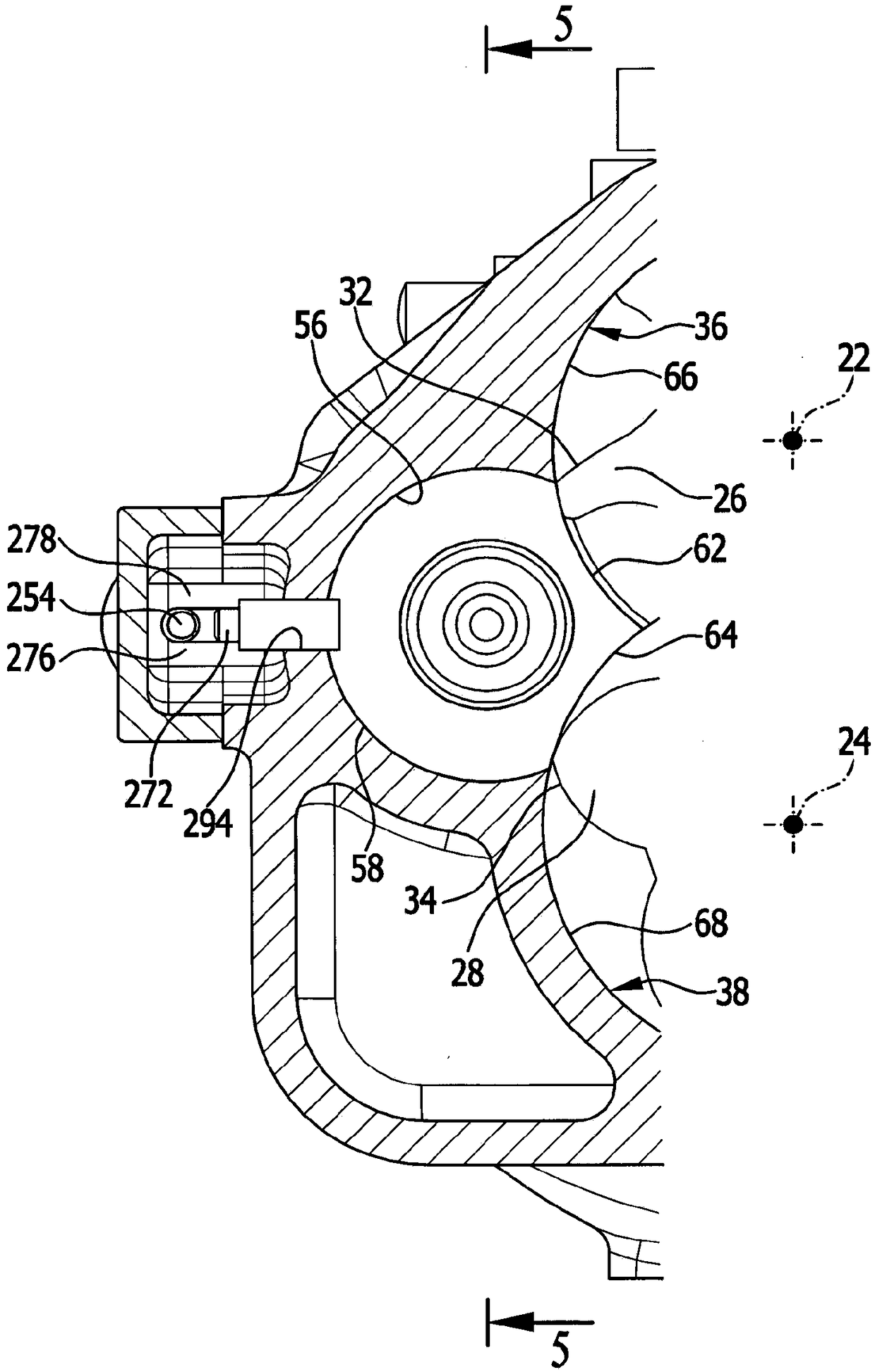
[0059] as in figure 2 with image 3 As shown in the figure, two screw movers 26, 28 that are rotatable around the screw mover axes 22, 24 respectively are arranged in the screw mover space 18 of the compressor housing 12, and the screw mover is characterized by its helical profile 32 and 34 engage with each other and cooperate with the compression wall 36 or 38 of the screw subspace 18 adjacent to the screw profile on the circumferential side in order to accommodate the pressure delivered to the low-pressure space 42 adjacent to the screw profile...


PUM


Abstract

Screw compressor comprising a compressor housing (12) with a screw rotor chamber which is arranged therein, two screw rotors (26, 28) which are arranged in the screw rotor chamber, are mounted such that they can be rotated in each case about a screw rotor axis on the compressor housing (12), and engage into one another by way of the screw contours thereof, and two control slides (52, 54) which arearranged in a slide channel (56) of the compressor housing so as to lie behind one another in a displacement direction which runs parallel to the screw rotor axis, adjoin the two screw rotors with slide compression wall surfaces, and can be moved in the displacement direction, wherein the first control slide (52) and the second control slide (54) can be moved, in a composite position with end sides which face one another, in the displacement direction in a manner which is joint and terminates sealingly with one another, and can be positioned at a spacing from one another in a separated position with the formation of an intermediate space, wherein the control slides form an inflow chamber (198) at least in a transition position which lies between the composite position and the separated position, into which inflow chamber (198) the medium to be compressed flows from one of the compression chambers, by virtue of the fact that it passes between the end sides of the control slides which face one another, and wherein one of the control slides is provided with at least one outflow outlet (212) which adjoins the inflow chamber and through which the medium from the inflow chamber (198) enters into an outflow opening (144) on the slide channel (56), which outflow opening (144) overlaps with the outflow outlet in said transition position.

Description

technical field [0001] The present invention relates to a screw compressor. The screw compressor includes: a compressor casing, the compressor casing has a screw mover space arranged therein; Screw runners mounted rotatably about their axes, the screw runners engaging one another with their helical contours and each cooperating with a compression wall adjoining the helical contour and partially surrounding the helical contour, in order to accommodate the The gaseous medium is conveyed from the low-pressure space in the housing and is discharged in the region of the high-pressure space arranged in the compressor housing, wherein the gaseous medium is contained at low pressure with a suction volume formed in the helical profile and adjoining the in a compression chamber between the compression walls of the helical profile and is compressed to a final volume under high pressure; and two successive directions of movement extending parallel to the axis of the helical mover in the s...

Claims


Application Information

Patent Timeline
Patent Type & Authority Applications(China)
IPC IPC(8): F04C28/12F04C18/16
CPCF04C28/12F04C18/16F04C18/023F04C28/185
Inventor 蒂霍米尔·米库利奇
Owner BITZER KUEHLMASCHINENBAU GMBH
Learn More