
Dual-flow centrifugal pump

a centrifugal pump and dual-flow technology, which is applied in the direction of motors, combination engines, working fluids for engines, etc., can solve the problems of significant impairment of the efficiency of the known centrifugal pumps and pump performance loss, and achieve the effect of smallest possible diameter and high efficiency

Inactive Publication Date: 2013-06-20
ALLWEILER
View PDF15 Cites 0 Cited by
  • Summary
  • Abstract
  • Description
  • Claims
  • Application Information

AI Technical Summary

Benefits of technology

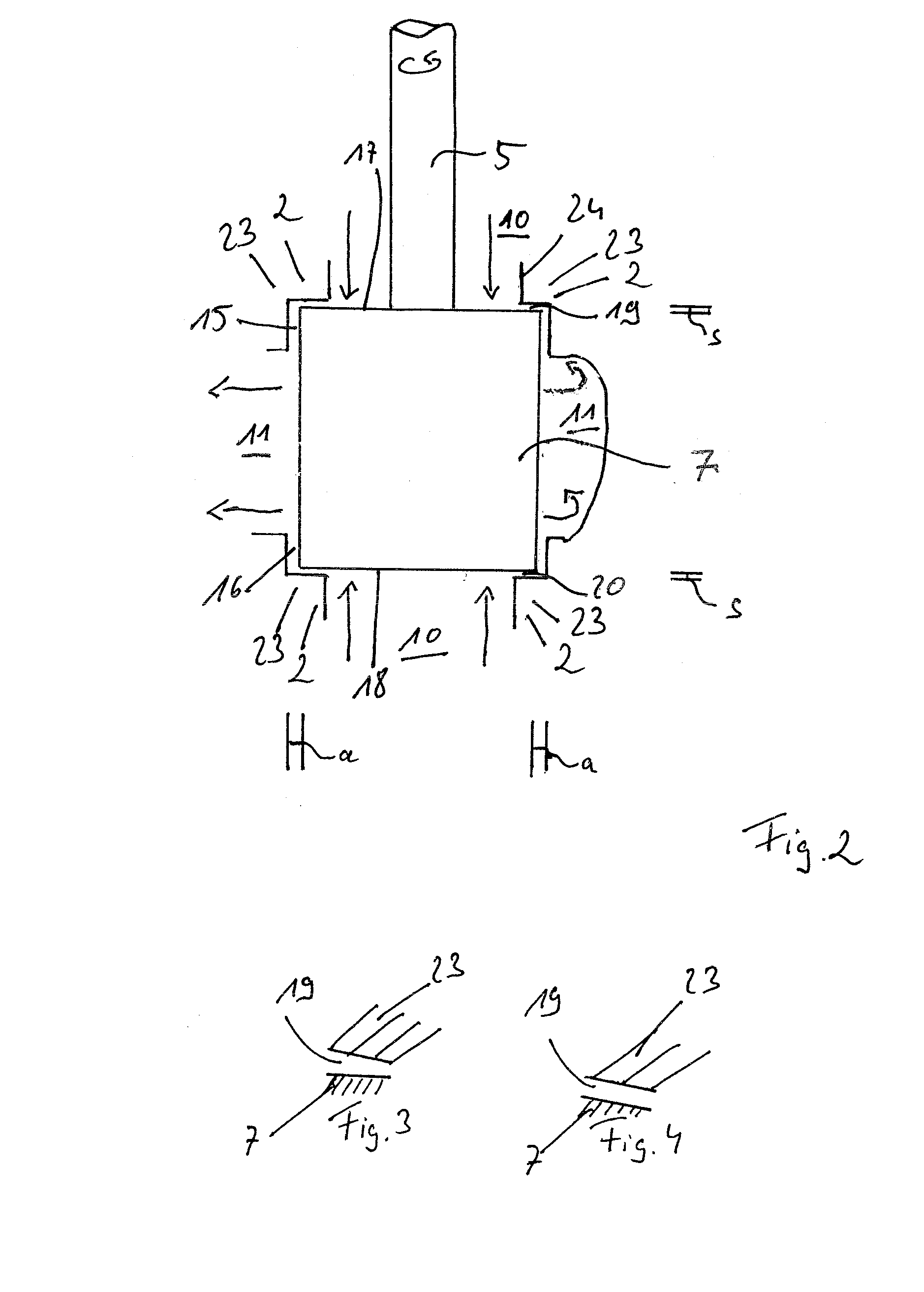
This patent describes a design for a centrifugal pump that improves sealing and efficiency. The design features two sealing gaps located inside the pump component, which prevent leakage and minimize the negative pressure area. The gaps are located as axial gaps, which allows for a smaller gap width compared to prior art designs. The dimensions of the gaps can be determined to prevent collisions even when the impeller is deflected during operation. This design allows for a high efficiency of the pump and a more compact size, particularly for marine applications. The minimal distance between the impeller and the pump component should be at least 2 mm to 10 mm to reliably prevent collisions.

Problems solved by technology

However, this results in a performance loss of the pump since constantly delivered medium from the radial positive pressure area flows in the axial direction through the sealing caps into the negative pressure area (suction area).
As a consequence, the efficiency of the known centrifugal pumps is significantly impaired.

Method used


Image

  • Dual-flow centrifugal pump
  • Dual-flow centrifugal pump
  • Dual-flow centrifugal pump

Examples


Embodiment Construction

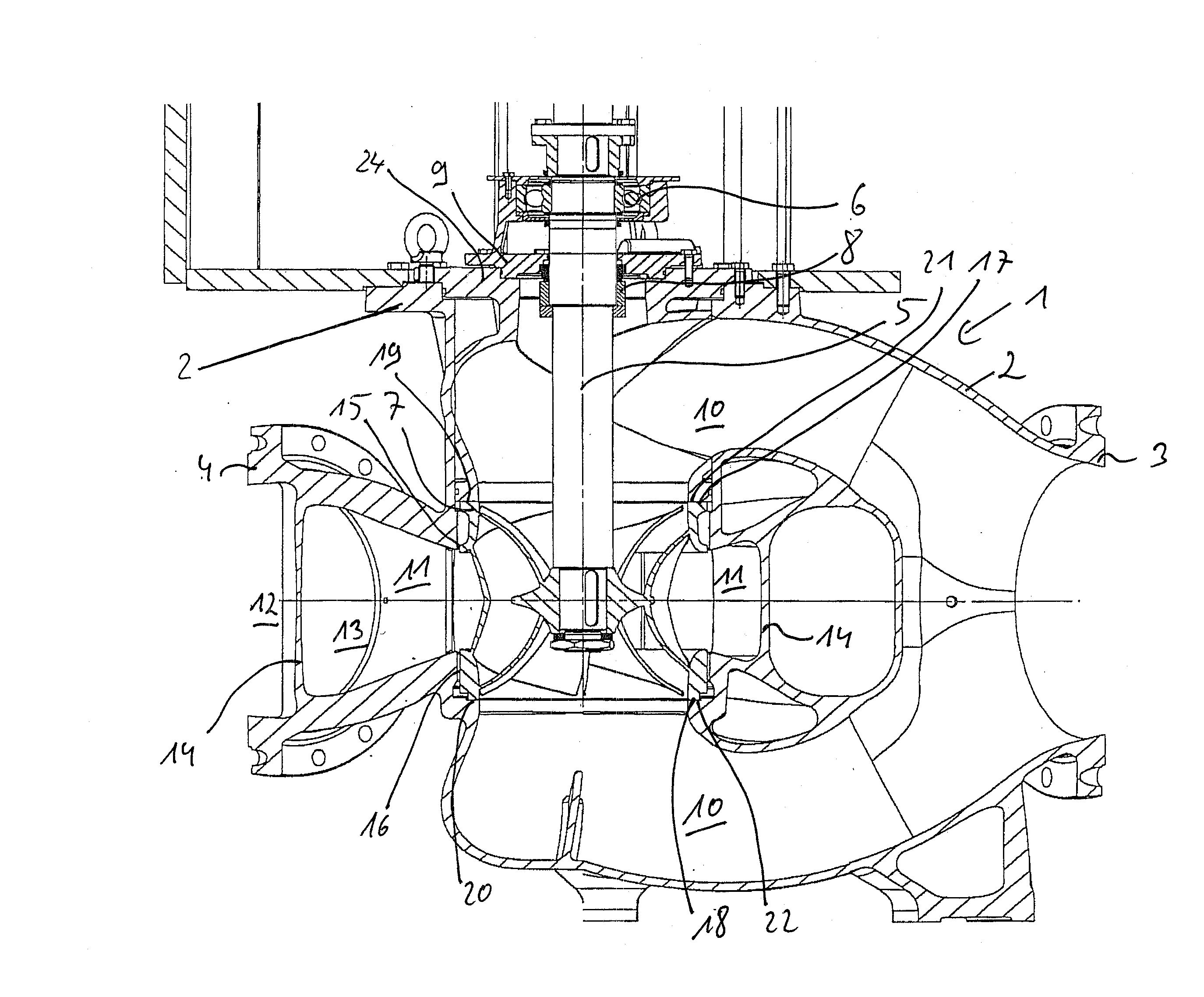
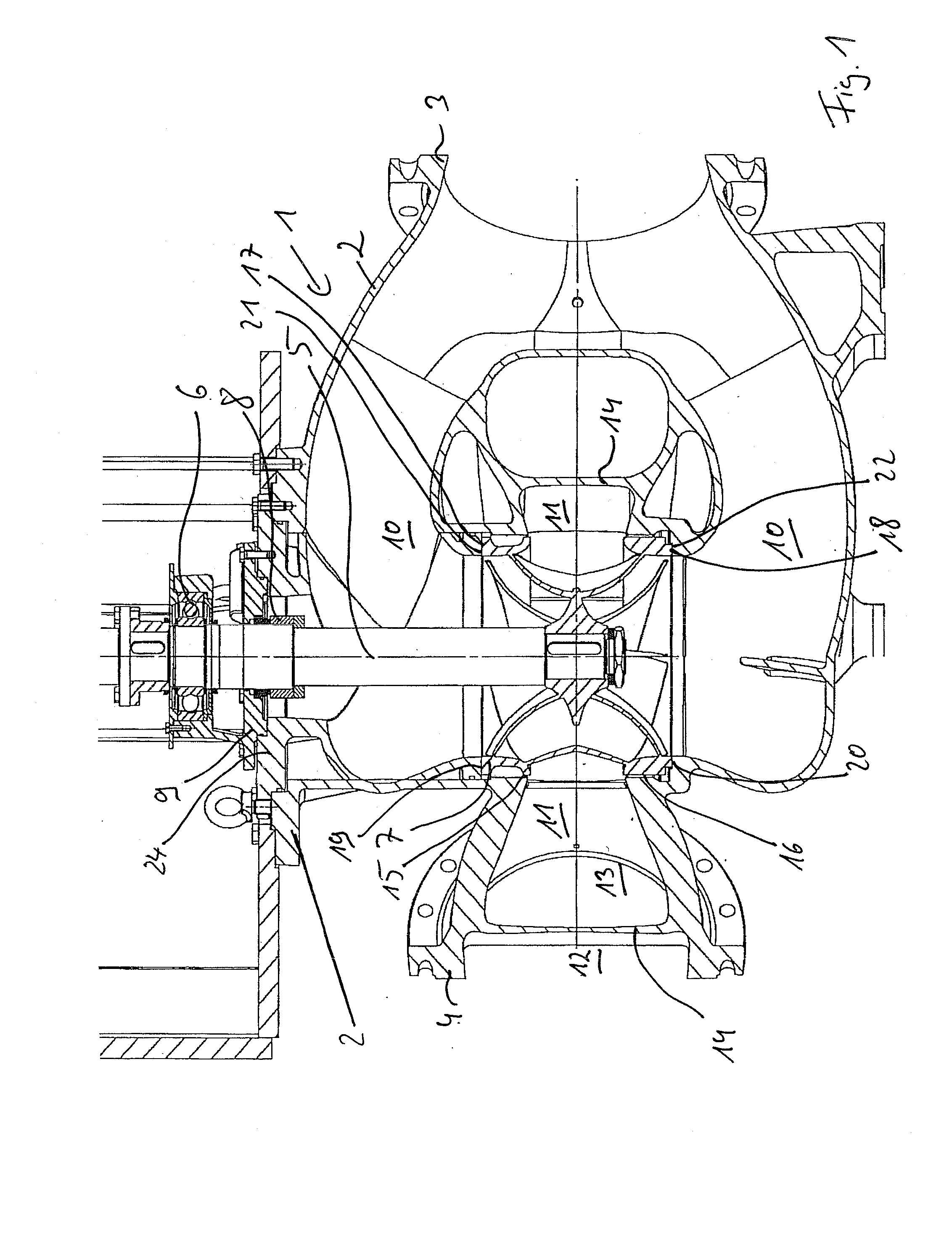
[0030]FIG. 1 shows a sectional view of a dual-flow centrifugal pump 1 in a vertical orientation (i.e., the impeller shaft is oriented vertically). The exemplary embodiment shown is a cooling water pump for a marine diesel engine designed for delivering a volume flow of 2300 m3 / h at a maximum delivery level of 30 m.

[0031]The centrifugal pump 1 comprises a pump housing 2 designed as a spiral housing and with a suction-side inlet 3 as well as a pressure-side outlet 4. A shaft 5 supported on one side extends into the pump housing 2 from above downward in a vertical direction and is supported by a bearing 6 constructed as a ball bearing. The shaft 5 carries on its inside a dual-flow impeller 7 with a substantially circularly cylindrical casing contour. The impeller 7 sits in a rotationally fixed manner on the shaft 5. A shaft seal 8 is located in an area axially between the support 6 and the impeller 7. As is apparent from FIG. 1 the shaft 5 extends in an area above the shaft seal 8 thro...


PUM


Abstract

A double-flow centrifugal pump is disclosed, in which, using an impeller, a fluid can be suctioned from two axial sides from a negative pressure area and can be delivered in the radial direction into a positive pressure area. The negative pressure area is sealed off with respect to the positive pressure area by at least one stationary pump component, for example the pump housing and / or an insert part. According to the invention, sealing gaps are formed as axial gaps arranged axially between the impeller and the pump component and extending in the circumferential direction and in the radial direction, wherein the gap width(s) of said axial gaps is less than the radial spacing (a) of the impeller from all the components arranged with a radial spacing from the impeller.

Description

FIELD OF THE INVENTION[0001]The invention relates to a preferably single-stage, double-flow centrifugal pump, in particular a cooling water pump for a marine diesel engine or a ballast water delivery pump on a ship, with a pump housing and with a dual-flow impeller rotationally fixedly arranged on a rotationally driven shaft, with which impeller a fluid can be suctioned from two axial sides from a negative pressure area (suction side) and delivered in the radial direction into a positive pressure area (pressure side), whereby the negative pressure area is sealed off with respect to the positive pressure area by means of at least two sealing gaps which are spaced apart axially (via the positive pressure area) and which are formed between the impeller and at least one stationary pump component, in particular the pump housing.BACKGROUND OF THE INVENTION[0002]In known dual-flow centrifugal pumps the sealing gaps, formed as annular gaps, run in the axial direction and are formed between ...

Claims


Application Information

Patent Timeline
IPC IPC(8): F04D1/00
CPCF04D1/006F04D1/00F04D29/167F04D29/086F04D29/406F05D2210/11Y10S415/00Y10S417/00
Inventor BRITSCH, MANFRED
Owner ALLWEILER
Learn More